


2
Installation, Operation & Maintenance HTV/HTD/HTH SERIES Heat Controller, Inc.
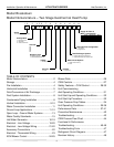
Model Breakdown
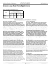
Model Nomenclature – Two Stage Geothermal Heat Pump
HT = Heat Controller Two Stage
C0 2 4 C1 0 1 A L K
4 5 6 7
8
91011121314
024
Unit Size
036
Return Air Flow Configuration
Voltage
C = CXM
Controls
B = Efficiency Upgrade
C = Microchannel Air Coil on 036
Revision Level
Heat Exchanger Options
Cabinet
Supply Air Flow &
Motor Configuration
HT
1 2
Series
V
3
V = Vertical Up Flow
H = Horizontal
D = Vertical Down Flow
Configuration
L = Left Return
R = Right Return
Water Circuit Options
048
060
0 = Residential
1 = HWG w/Internal Pump
0 = None
Supply Configuration Motor
K
N
P
W
HTV
HTD
HTH
HTH
Top
Down
Back
Straight
ECM
ECM
ECM
ECM
070
1 = 208-230/30/1
A = Copper Water Coil, Coated Air Coil
J = Copro-Nickel Water Coil, Coated Air Coil
TABLE OF CONTENTS
Model Nomenclature ..........................................2
Storage ...............................................................4
Pre-Installation....................................................4
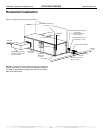
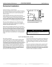
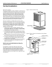
Horizontal Installation .........................................5
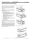
Field Conversion of Air Discharge ......................7
Duct System Installation .....................................8
Condensate Piping Installation ...........................8
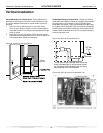
Vertical Installation........................................ 9-10
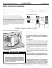
Water Connection Installation ...........................11
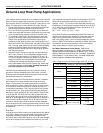
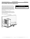
Ground Loop Applications ...........................11-12
Open Loop - Ground Water Systems ...............13
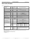
Water Quality Standards ..................................15
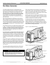
Hot Water Generator .................................. 16-18
Electrical - Line Voltage .............................. 19-20
Electrical - Low Voltage Wiring ................... 21-22
Accessory Connections ....................................22
Electrical - Thermostat Wiring ..........................23
ECM Blower Control ................................... 24-25
Blower Data ......................................................26
CXM Controls ...................................................27
Safety Features – CXM Control.................. 28-30
Unit Commissioning
And Operating Conditions ................................31
Unit Start-Up and Operating Conditions ...........32
Unit Start-Up Procedure ...................................32
Coax Pressure Drop Tables ..............................34
Unit Operating Conditions .......................... 35-36
Performance Data ...................................... 37-41
Preventive Maintenance ...................................42
Troubleshooting ................................................43
CXM Process Flow Chart .................................44
Functional & Performance
Troubleshooting .......................................... 45-46
Troubleshooting Form ......................................47
Refrigerant Circuit Diagram ..............................47
Revision History................................................48