


12
Installation, Operation & Maintenance HTV/HTD/HTH SERIES Heat Controller, Inc.
Ground-Loop Heat Pump Applications
most areas to prevent freezing. All air and debris must be removed
from the earth loop piping before operation. Flush the loop with a
high volume of water at a minimum velocity of 2 fps (0.6 m/s) in all
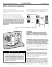
piping. The steps below must be followed for proper fl ushing.
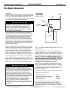
1. Fill loop with water from a garden hose through the fl ush cart
before using the fl ush cart pump to insure an even fi ll.
2. Once full, the fl ushing process can begin. Do not allow the
water level in the fl ush cart tank to drop below the pump inlet
line to avoid air being pumped back out to the earth loop.
3. Try to maintain a fl uid level in the tank above the return tee
so that air cannot be continuously mixed back into the fl uid.
Surges of 50 psi (345 kPa) can be used to help purge air
pockets by simply shutting off the return valve going into the
fl ush cart reservoir. This “dead heads” the pump to 50 psi (345
kPa). To purge, dead head the pump until maximum pumping
pressure is reached. Open the return valve and a pressure
surge will be sent through the loop to help purge air pockets
from the piping system.
4. Notice the drop in fl uid level in the fl ush cart tank when the
return valve is shut off. If air is adequately purged from the
system, the level will drop only 1-2 inches (2.5 - 5 cm) in a
10” (25 cm) diameter PVC fl ush tank (about a half gallon [2.3
liters]), since liquids are incompressible. If the level drops
more than this, fl ushing should continue since air is still
being compressed in the loop fl uid. Perform the “dead head”
procedure a number of times. Note: This fl uid level drop is
your only indication of air in the loop.
Antifreeze may be added before, during or after the fl ushing
procedure. However, depending upon which time is chosen,
antifreeze could be wasted when emptying the fl ush cart tank.
See antifreeze section for more details.
Loop static pressure will fl uctuate with the seasons. Pressures
will be higher in the winter months than during the cooling
season. This fl uctuation is normal and should be considered
when charging the system initially. Run the unit in either heating
or cooling for a number of minutes to condition the loop to a
homogenous temperature. This is a good time for tool cleanup,
piping insulation, etc. Then, perform fi nal fl ush and pressurize
the loop to a static pressure of 50-75 psi [345-517 kPa] (winter)
or 35-40 psi [241-276 kPa] (summer). After pressurization, be
sure to loosen the plug at the end of the Grundfos loop pump
motor(s) to allow trapped air to be discharged and to insure the
motor housing has been fl ooded. This is not required for Taco
circulators. Insure that the Flow Controller provides adequate
fl ow through the unit by checking pressure drop across the heat
exchanger and compare to the pressure drop tables at the back
of the manual.
Antifreeze
In areas where minimum entering loop temperatures drop below
40°F [5°C] or where piping will be routed through areas subject
to freezing, antifreeze is required. Alcohols and glycols are
commonly used as antifreeze; however your local sales manager
should be consulted for the antifreeze best suited to your area.
Low temperature protection should be maintained to 15°F [9°C]
below the lowest expected entering loop temperature. For
example, if 30°F [-1°C] is the minimum expected entering loop
temperature, the leaving loop temperature would be 25 to 22°F
[-4 to -6°C] and low temperature protection should be at 15°F
[-10°C]. Calculation is as follows:
30°F - 15°F = 15°F [-1°C - 9°C = -10°C].
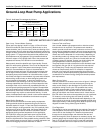
All alcohols should be premixed and pumped from a reservoir
outside of the building when possible or introduced under the
water level to prevent fumes. Calculate the total volume of
fl uid in the piping system. Then use the percentage by volume
shown in Table 2 for the amount of antifreeze needed. Antifreeze
concentration should be checked from a well mixed sample
using a hydrometer to measure specifi c gravity.
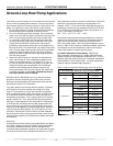
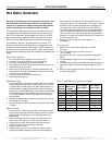
Table 1: Approximate Fluid Volume (gal.) per 100' of Pipe
Fluid Volume (gal [liters] per 100’ [30 meters) Pipe)
Pipe Size Volume (gal) [liters]
Copper
1” 4.1 [15.3]
1.25” 6.4 [23.8]
2.5” 9.2 [34.3]
Rubber Hose 1” 3.9 [14.6]
Polyethylene
3/4” IPS SDR11 2.8 [10.4]
1” iPS SDR11 4.5 [16.7]
1.25” IPS SDR11 8.0 [29.8]
1.5” IPS SDR11 10.9 [40.7]
2” IPS SDR11 18.0 [67.0]
1.25” IPS SCH40 8.3 [30.9]
1.5” IPS SCH40 10.9 [40.7]
2” IPS SCH40 17.0 [63.4]
Unit Heat Exchanger Typical 1.0 [3.8]
Flush Cart Tank
10” Dia x 3ft tall
[254mm x 91.4cm tall]
10 [37.9]
Low Water Temperature Cutout Setting - CXM Control
When antifreeze is selected, the FP1 jumper (JW3) should be
clipped to select the low temperature (antifreeze 10°F [-12.2°C])
set point and avoid nuisance faults (see “Low Water Temperature
Cutout Selection” in this manual). Note: Low water temperature
operation requires extended range equipment.