


16
Installation, Operation & Maintenance HTV/HTD/HTH SERIES Heat Controller, Inc.
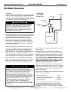
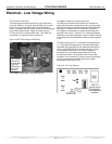
Electric water heaters are recommended. If a gas, propane, or
oil water heater is used, a second preheat tank must be installed
(Figure 15). If the electric water heater has only a single center
element, the dual tank system is recommended to insure a usable
entering water temperature for the HWG.
Typically a single tank of at least 52 gallons (235 liters) is used to
limit installation costs and space. However, a dual tank, as shown
in Figure 15, is the most effi cient system, providing the maximum
storage and temperate source water to the HWG.
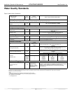
It is always advisable to use water softening equipment on
domestic water systems to reduce the scaling potential and
lengthen equipment life. In extreme water conditions, it may be
necessary to avoid the use of the HWG option since the potential
cost of frequent maintenance may offset or exceed any savings.
Consult Table 3 for scaling potential tests.
Hot Water Generator
The HWG (Hot Water Generator) or desuperheater option
provides considerable operating cost savings by utilizing excess
heat energy from the heat pump to help satisfy domestic hot
water requirements. The HWG is active throughout the year,
providing virtually free hot water when the heat pump operates
in the cooling mode or hot water at the COP of the heat pump
during operation in the heating mode. Actual HWG water
heating capacities are provided in the appropriate heat pump
performance data.
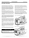
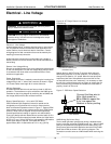
Heat pumps equipped with the HWG option include a built-in
water to refrigerant heat exchanger that eliminates the need to
tie into the heat pump refrigerant circuit in the fi eld. The control
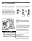
circuit and pump are also built in for residential equipment. Figure
14 shows a typical example of HWG water piping connections on
a unit with built-in circulating pump. This piping layout reduces
scaling potential.
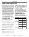
The temperature set point of the HWG is fi eld selectable to 125°F
or 150°F . The 150°F set point allows more heat storage from
the HWG. For example, consider the amount of heat that can be
generated by the HWG when using the 125°F set point, versus
the amount of heat that can be generated by the HWG when
using the 150°F set point.
In a typical 50 gallon two-element electric water heater the lower
element should be turned down to 100°F, or the lowest setting,
to get the most from the HWG. The tank will eventually stratify
so that the lower 80% of the tank, or 40 gallons, becomes 100°F
(controlled by the lower element). The upper 20% of the tank, or
10 gallons, will be maintained at 125°F (controlled by the upper
element).
Using a 125°F set point, the HWG can heat the lower 40 gallons
of water from 100°F to 125°F, providing up to 8,330 btu’s of heat.
Using the 150°F set point, the HWG can heat the same 40 gallons
of water from 100°F to 150°F and the remaining 10 gallons of
water from 125°F to 150°F, providing a total of up to 18,743 btu’s
of heat, or more than twice as much heat as when using the
125°F set point.
This example ignored standby losses of the tank. When those
losses are considered the additional savings are even greater.
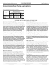
Figure 14: Typical HWG Installation
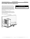
Figure 15: HWG Double Tank In stal la tion
WARNING!
WARNING!
A 150°F SETPOINT MAY LEAD TO
SCALDING OR BURNS. THE 150°F SET POINT MUST
ONLY BE USED ON SYSTEMS THAT EMPLOY AN
APPROVED ANTI-SCALD VALVE.
Hot Outlet
to home
Insulated water lines -
5/8” OD, 50 ft maximum (one way)
[16mm OD, 15 meters maximum]
Powered
Water
Heater
Upper
element to
120 - 130°F
[49 - 54°C]
Lower
element to
100 - 110°F
[38 - 43°C]
Shut-off
Valve #3
Shut Off
Valve #2
Field supplied 3/4’ brass nipple and ‘T’
Cold
Inlet
Shut Off
Valve #4
Shut Off
Valve #1
Insulated water lines - 5/8” OD, 50 ft maximum (one way)
[16mm OD, 15 meters maximum]
Upper element to 130°F [54°C]
(or owner preference)
Cold Inlet
Hot Outlet to
house
Powered
Water Heater
Cold Inlet from
Domestic supply
Hot Outlet
Unpowered
Water Heater
Field Supplied 3/4” brass nipple and “T”
Lower element to 120°F [49°C]
Shut-off
Valve #1
Shut-off
Valve #4
Shut-off
Valve #3
Shut Off
Valve #2