


9
Connecting the Linesets
IMPORTANT NOTES FOR HORIZONTAL OR
DOWNFLOW INSTALLATIONS WITH TXV VALVE:
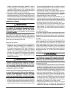
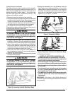
• The sensing bulb must be located flush against the
suction line for optimum heat transfer.
• Avoid attaching the sensing bulb to the lowest part of
the suction line where condensate may accumulate.
• Do not locate the sensing bulb on vertical sections
of the lineset.
• For horizontal lines, the bulb should not be located
at 12 or 6 o’clock position of the suction line. The
best location is at 4 or 8 o’clock.
• For additional information on proper sensing bulb
locations, please refer to the valve manufacturer’s
instructions.
IMPORTANT: The steps in the Orifice Removal &
Installation section must be performed before the linesets
are connected.
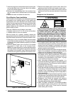
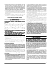
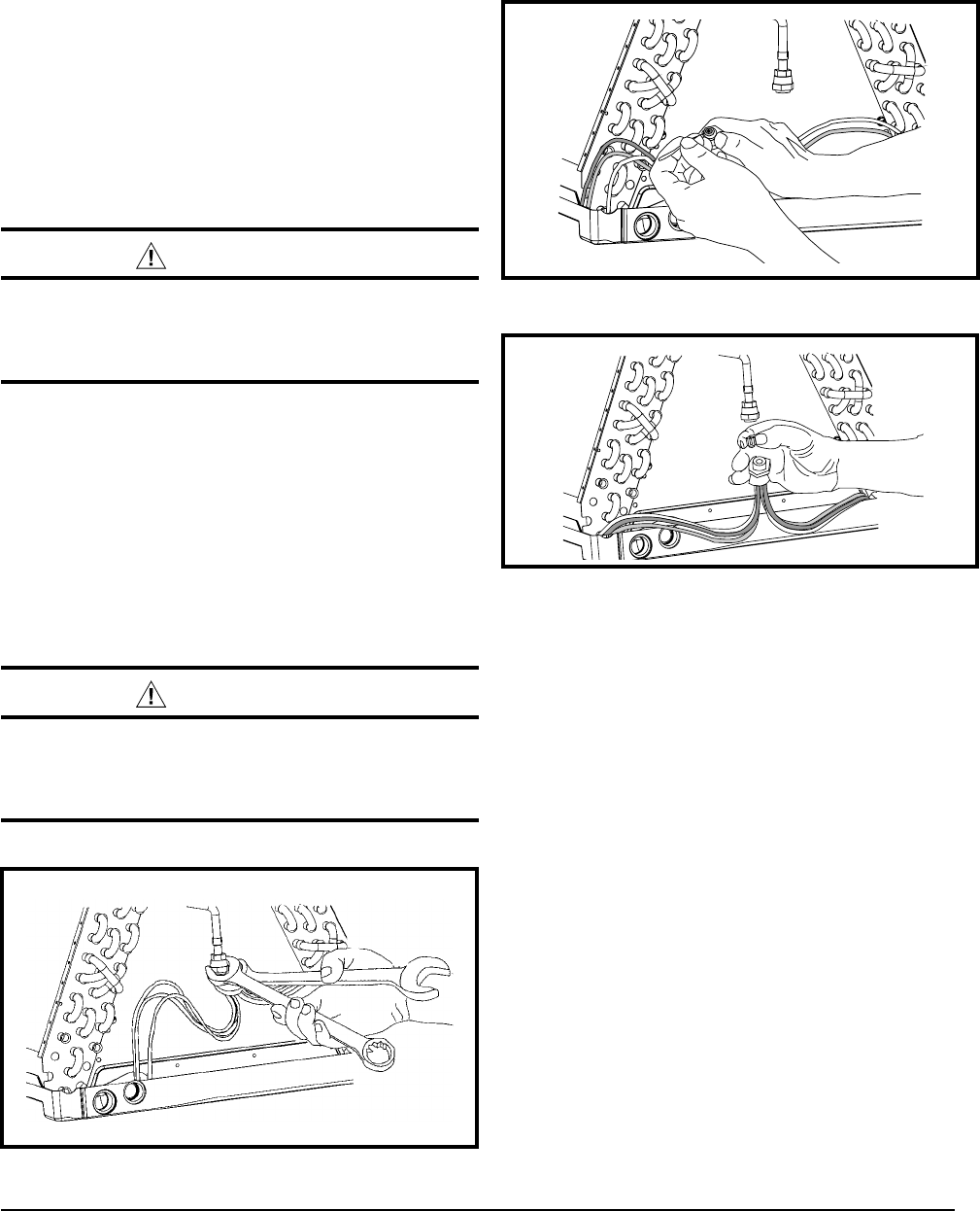
Figure 8. Restrictor Insertion into Distributor Body
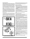
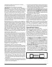
Figure 7. Removal of Orifice
9. Realign the assembly nut on the distributor body and
hand tighten both components. Mark a line on both
bodies and then tighten an additional 1/4 turn using two
wrenches. The movement of the two lines will show how
much the nut is tightened. If a torque wrench is used,
tighten to 10-12 ft. lbs. or 14-16 Nm.
Orifice Removal & Installation
The orifice installed in the air handler has been sized for
use with the most popularly matched outdoor units. The
orifice size as shipped from the factory is listed on the air
handler rating plate. Perform steps 1 - 9 to confirm that
the orifice size meets the requirements outlined in the
outdoor unit installation manual.
1. Remove the cap from the end of the liquid line.
2. Verify pressurization by depressing the Schrader valve
on the end of the liquid line. Listen for any escaping gas.
If there is no pressure, test the coil for leakage.
• Ifleakageisfound,clearlymarkthelocationoftheleak
and return the coil to the distributor for processing.
• Ifnoleaksarefound,thecoilmaybeinstalled.
3. Depress the valve to relieve all pressure from the coil.
4. Remove and discard the valve core.
CAUTION:
To prevent damage to the unit or internal
components, it is recommended that two
wrenches be used when loosening or tightening
nuts. Do not over tighten!
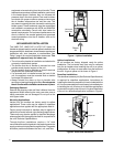
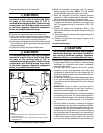
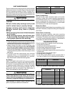
5. Using two wrenches, loosen the nut and distributor body
as shown in Figure 6. Turn the assembly nut counter-
clock-wise until the orifice body halves are seperated.
6. Insert a light-gauge wire hook between the distributor
body and the restrictor orifice while being careful not
to scratch either part. Carefully remove the restrictor
orifice from the distributor body. See Figure 7.
7. Check the actual size of the new orifice. NOTE: The
size is stamped on its side. Do not use pin gauges to
measure the orifice diameter.
8. Insert the new orifice into the distributor body, rounded
end down. See Figure 8.
CAUTION:
To prevent damage to the unit or internal
components, it is recommended that two
wrenches be used when loosening or tightening
nuts. Do not over tighten!
Figure 6. Loosening of Nut & Distributor Body