


10
6. Braze the individual connections with dry nitrogen
flowing through the joints. NOTE: This will prevent
internal oxidation and scaling from occurring.
7. Wrap the refrigerant lines with pressure sensitive
neoprene or other suitable material especially where
the lines enter the opening in the sheet metal.
8. Evacuate the system of moisture and non-condensables
to prevent low efficiency operation or damage to the
unit. The suggested range of evacuation is 350 - 500
microns.
9. Charge the system with refrigerant. Refer to the
outdoor unit installation manual for additional charging
instructions.
10. Check the system for leaks, including the lineset and
the brazed joints.
11. Replace all grommets and properly dispose of all
removed parts.
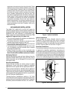
Condensate Drainage
CAUTION:
The air handler must be level to ensure proper
condensate drainage. An unlevel installation
may result in structural damage, premature
equipment failure, or possible personal injury.
• Methodsfordisposingofcondensatevaryaccording
to local codes. Refer to local codes or authority having
jurisidiction for restrictions and proper condensate
disposal requirements.
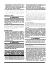
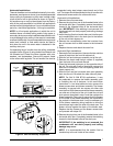
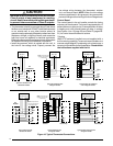
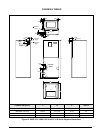
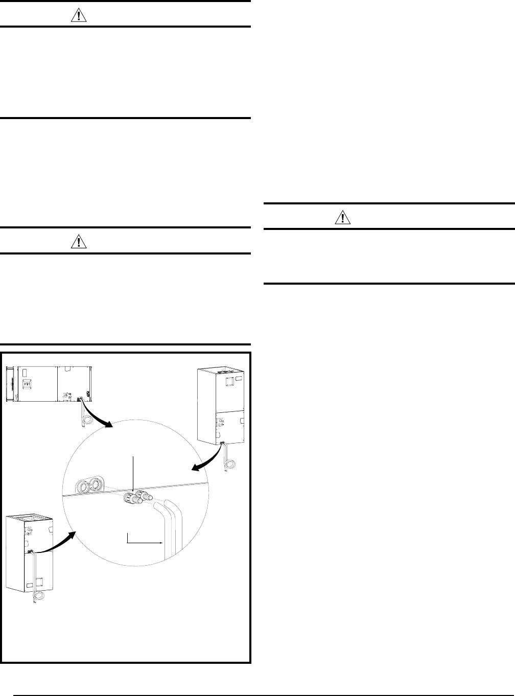
• The drain pan that is supplied with this air handler
contains a primary and secondary drain fitting. The
condensate is drained from the unit through two 3/4”
female pipe fittings located on the front side of the unit
as shown in Figure 9.
• Thedrainpanmustbedrainedwitheldsuppliedtubing
or pvc pipe and adequately trapped. Both drain tubes
must have a minimum diameter of 3/4” and be trapped
separately.
IMPORTANT: Failure to install a trap may result in
condensation overflowing the drain pan, resulting in
substantial water damage to surrounding area.
• Routebothlinestoasuitabledrain,avoidingsharpbends
and pinching of the lines. The drain should maintain a
minimum horizontal slope in the direction of discharge
of not less than 1” vertical for every 10 ft of horizontal
run.
• Iftheairhandlerislocatedinorabovealivingspace
where damage may result from condensate overflow,
an auxiliary drain pan shall be installed under the unit.
A separate drain line should extend from the pan to a
conspicuous point and serve as an alarm indicating
that the primary drain is restricted. As an alternative to
a separate drain line, an approved water level indicator
or float switch device may be used to shut down the
unit in the event water is detected in the auxiliary pan.
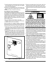
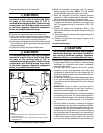
1. Remove grommets from line set holes.
CAUTION:
It is recommended that a wet rag be wrapped
around the suction line in front of the close
off plate or the sensing bulb (if TXV is
installed) before applying heat. Failure to keep
components cool during brazing may result
in structural damage, premature equipment
failure, or possible personal injury.
2. Unbraze and remove the cap on the suction line.
3. Route and cut both lineset tubes to proper length in
accordance with the outdoor unit specifications. Verify
the ends are round, clean, and free of any burrs.
4. Position grommet on line set with sufficient distance away
from brazing area. Brazing processes can permanently
damage grommets.
5. Connect the suction and liquid lineset tubes.
CAUTION:
It is recommended that a wet rag be wrapped
around the suction line in front of the close
off plate or the sensing bulb (if TXV is
installed) before applying heat. Failure to keep
components cool during brazing may result
in structural damage, premature equipment
failure, or possible personal injury.
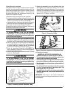
3/4” Adapter w/
3/4” dia. hose barb
3/4” minimum dia.
PVC or flexible tubing
HORIZONTAL
UPFLOW
DOWNFLOW
NOTES:
1. The drain lines must maintain a downward slope to ensure proper
condensate drainage.
2. Each condensate drain must be trapped separately using a J-Trap or
field supplied loop.
Figure 9. Condensate Drainage Example