


8
Refrigerant Line Connections
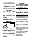
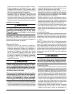
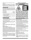
WARNING:
The coil in the air handler is factory shipped with
a nitrogen charge. Avoid direct face exposure
or contact with valve when gas is escaping.
Always ensure adequate ventilation is present
during the depressurization process. Address
any uncertainties before proceeding. Failure
to comply with this warning could result in
equipment damage, personal injury, or death.
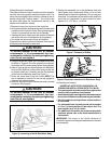
NITROGEN
HEALTH
FLAMMABILITY
REACTIVITY
0 Minimal Hazard
1 Slight Hazard
1
0
0
• Theinstallershouldmakeeveryefforttoensurethe
field installed refrigerant containing components of the
system have been installed in accordance with these
instructions and sound installation practices for reliable
system operation and longevity.
• Theairhandlercoildoesnotcontainarefrigerantcharge.
Refer to the installation instructions supplied with the
outdoor unit for refrigerant charge information.
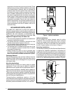
• Alwaysrefertotheinstallationinstructionssuppliedwith
the outdoor unit for piping requirements. The suction
and liquid lines must be sized in accordance with the
condensing unit specifications. See Figure 12 (page
17) for liquid and suction line locations.
• When connecting refrigerant linesets together, it is
recommended that dry nitrogen be flowing through the
joints during brazing. This will prevent internal oxidation
and scaling from occurring.
• Refrigeranttubingshouldberoutedinamannerthat
minimizes the length of tubing and the number of bends
in the tubing. It should be supported in a manner that
prevents it from vibrating or abrading during system
operation. Tubing should be kept clean of foreign debris
during installation.
• Ifpreciseformingofrefrigerantlinesisrequired,acopper
tubing bender is recommended. Avoid sharp bends and
contact of the refrigerant lines with metal surfaces.
• Refrigerant lines should be wrapped with pressure
sensitive neoprene or other suitable material where
they pass against sharp sheet metal edges.
• HMG**F1E, HMG**X1E & HCG**V1E Series air handlers
are charged through service valves on the end of the
liquid tube for each circuit. These must be removed
before brazing the line sets.
7. Insert the plug (from horizontal drain pan) into the open
and unused drain hole in the drain pan at the bottom
of the unit to block bypass air.
8. Remove the corresponding drain line knockout from
the coil access door to allow access to the horizontal
drain.
9. Replace the door and attach the drain line
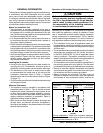
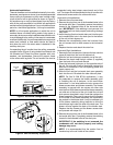
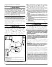
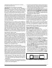
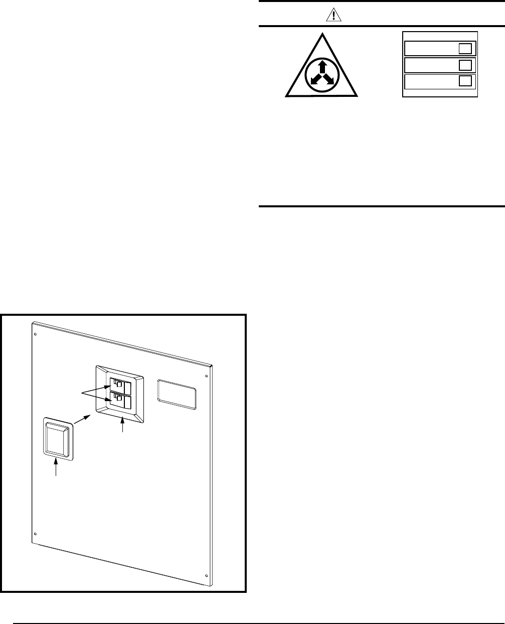
Circuit Breaker Cover Installation
The air handler circuit breaker cover is designed to protect
the breakers of an installed heater kit from debris and
condensation.The cover attaches to the breaker recess
of the air handler upper access door using a double-sided
adhesive gasket. See Figure 5. The heater kit circuit
breaker toggles are still accessible and can be switched
with the cover in place.
There are 2 different circuit breaker cover sizes:
• 2-breakercoverfor2,2.5,3,3.5,&4tonairhandlers.
• 3-breakercoverfor5tonairhandlers.
After the heater kit is properly installed, remove the
appropriate knockouts in the upper air handler access door
and follow these instructions to install the breaker cover:
1. Clean any oil, dirt, or insulation fibers from the recess
area of the air handler access door. This step is important
for ensuring the gasket adheres properly to the sheet
metal door.
2. Remove release paper from one side of the gasket
and attach to back side of the breaker cover.
NOTE: For proper alignment, It is recommended to leave
the center section of the gasket in place when attaching
the gasket to the breaker cover. Remove the center
section after the gasket is applied to the breaker cover.
Circuit Breaker
Cover
Circuit
Breakers
Recess
Air Handler Access Door
Figure 5. Circuit Breaker Cover
3. Remove the release paper from the other side of the
gasket and attach to the circuit breaker recess area.
4. Press firmly along all four sides of the cover to ensure
gasket and cover are securely attached to the access
door.