


15
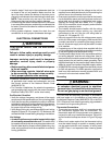
4. Replace the upper door and secure it to the unit.
5. Restore power to the unit.
High Efficiency Units (Variable & Fixed Speed)
IMPORTANT! This air handler has been designed to
give the installer maximum flexibility to optimize system
performance, efficiency, and comfort. Because there
are so many different ways to set up the air handler it is
important to read and follow these directions carefully.
HMG**X1E & HCG**V1E series air handlers use high
efficiency circulating air motors that come in two variations
and both are controlled differently. The fixed speed motor
control board (Figure 16, page 24) controls the torque
and the variable speed motor control board (Figure 17)
controls the airflow at a constant CFM. Both boards use
the same control board.
Before operation, the air handler must be configured to
match the unit with the system, system options, and climatic
conditions. When configured, the air handler responds
directly to the thermostat inputs, as well as the optional
humidistat (see page 13). During normal operation, the
motor will gradually change speeds during start-up, shut
down, when thermostat inputs change, and when the duct
static pressure changes (vents closed or opened, filter
clogging, etc.). The air handler is configured by setting
the selector switches and removing jumper connectors.
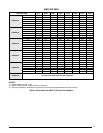
Selecting Basic Heating Airflow
Fixed & variable speed motor control boards (Figures 16
& 17) contain a set of dip switches for setting the blower
speed. For HMG**X1E models, pins 1-4 set the speed for
heating. For HCG**V1E models, the A/B switch must be
set for the appropriate air handler size (either setting can
be used for 48K or 60K BTUH applications). The airflow is
set automatically based on the amount of installed heat.
For both HMG**X1E & HCG**V1E models, the cooling
speed is selected via switches 5,6,7,& 8. To determine
the appropriate switch settings for your installation, see
Tables 6, 7, 8, or 9 (pages 20 - 22).
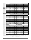
Selecting Basic Cooling / Heat Pump Airflow
The basic cooling/heat-pump airflow is controlled by setting
switches 5 - 8 on the motor control board (mounted on the
blower). All airflows for other modes of operation (except
electric heat) are determined by this basic setting. FAN
ONLY would deliver 50% of the selected cooling airflow.
Table 8 (page 21) lists the basic airflow values versus the
airflow selector switch settings and ranges of basic air flow
settings recommended for each nominal system capacity.
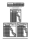
• When operating in the heat pump mode, a higher
basic airflow setting will increase the energy efficiency
and capacity but will also decrease the supply air
temperature.
• For maximum capacity and energy efficiency, select an
airflow at or near the top of the range for that nominal
capacity. See Table 8 (page 21).
• Formaximumdehumidication,selectanairownearthe
middle or bottom of the range for that nominal capacity.
Additional information on humidity control can be found
in the Humidistat and Delay Setting sections.
• Forthermostatswithadehumidieroutput,useaeld
supplied wire to connect the thermostat’s dehumidifier
output to the terminal marked DHUM. The thermostat
should be set so that the DHUM output should be high
(energized) when dehumidification is needed. See also
Dehumidification Options section.
IMPORTANT! If coil icing is observed, the basic cooling/
heat-pump airflow selected may be too low. Verify the
setting selected is within the range shown in Table 8 and
that the the system is properly charged. Please refer to the
instructions supplied with the outdoor unit. If icing continues
to occur, raise the selected airflow one or two steps.
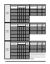
NOTE: Variable speed air handlers with SEER ratings
higher than 15 are matched with a 2-stage cooling outdoor
unit. They are programmed to operate at 75% of the
selected airflow while the system is in the lo-cool mode
and 100% of the selected airflow while in hi-cool mode.
Dehumidification Options
(HMG**X1E or HCG**V1E Models Only)
Both motor control boards (Figures 16 & 17, page 24)
have a DHUM connection that allows the system to
increase the amount of humidity that is removed from
the circulating air. This is accomplished by reducing the
CFM and allowing the cooling coil to become colder. This
will only occur when there is a call for cooling. There are
many ways that this can be electrically wired.
1. If the room thermostat incorporates a humidity sensor
and DHUM output, connect the DHUM on the thermostat
to the DHUM terminal on the motor control board.
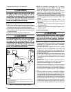
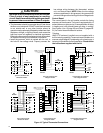
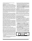
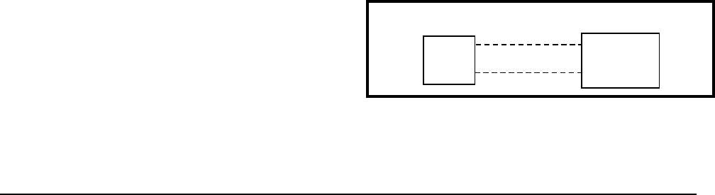
2. If using a separate humidistat, connect the DHUM & R
terminals on the humidistat to the DHUM & R terminals
on the motor control board of the air handler. In this
option, the DHUM output of the humidistat must be set
to be normally open and closed when there is a call for
humidification. See Figure 11.
3. If a humidistat is not available, it is an acceptable option
to connect the R & DHUM terminals on the motor
control board together with a field supplied wire. This
option causes the blower to run at a reduced CFM for
10 minutes after a call for cooling. NOTE: If outdoor
unit is a heat pump, connect the O terminal to DHUM.
DHUM
R
R
DHUM
HUMIDISTAT
MOTOR
CONTROL BOARD
Figure 11. DHUM Wiring Configuration