


14
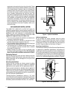
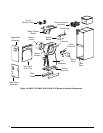
Blower Configurations
Determining Nominal System Capacity
To select the appropriate airflows for the air handler, the
nominal system capacity must be known. The nominal
system capacity is always the nominal capacity of the
outdoor unit. However, in some situations the nominal
system capacity may not be the same as the nominal
capacity of the air handler. Always refer to the nominal
capacity of the outdoor unit to determine the nominal
system capacity.
NOTE: The CFM values listed in Table 9 (page 22) are
not dependent on duct static pressure. The VSHE motor
automatically compensates for changes in duct static
pressure (within the limits of the motor).
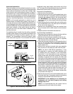
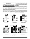
3-Speed Units
The blower speed is preset at the factory for operation
at the same speed for heating and cooling, by using the
jumping terminal on the blower motor and connecting it
to the desired speed with both the red and black wires
connected to the jumping terminal. NOTE: The control
board is programmed with a 40 second off delay in the
cooling mode for optimum system performance and
efficiency.
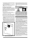
CAUTION:
To avoid personal injury or property damage,
make sure the motor leads do not come into
contact with any uninsulated metal components
of the unit.
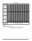
For optimum system performance and comfort, it may be
necessary to change the factory set speed. See Table 5
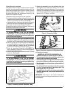
(page 19) for airflow data. To change the blower speed:
1. Disconnect all electrical power to the unit and remove
the upper door.
2. Remove the black and red wires from the blower motor
jumping terminal. Discard the blower motor jumping
terminal.
3. Connect the heating speed wire (red) and the cooling
speed wire (black) to the desired blower speed marked
on the terminal block of the blower motor.
• Terminal4=Hispeed
• Terminal5=Medspeed
• Terminal6=Lowspeed
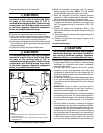
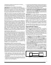
Refrigerant Charging
The system refrigerant charge can be checked and
adjusted through the service ports provided at the front
panel of the outdoor unit. Use only gauge lines which have
a Schrader depression device present to actuate the valve.
Air Circulation
Running the Blower Continuously
Set the thermostat’s system mode to OFF and the
thermostat’s fan mode to ON. The blower motor should
run continuously. Check for air delivery at the register(s).
Ensure that there are no obstructions at the registers or
in the ducts.
Selecting continuous low speed fan operation
(Standard Blower)
The air handler is equipped with an option of continuous
low speed fan operation. When G is energized without Y/
Y2, the air handler will operate using the cooling speed.
With G & Y/Y2 or Y/Y2 energized, the air handler will
operate in the selected cooling speed (including 40 sec
blower-off delay).
Turning the Blower Off
Set thermostat’s fan mode to AUTO, the blower will shut
down immediately.
System Cooling
1. Set the thermostat’s system mode to COOL and fan
mode to AUTO. Lower the thermostat’s temperature
mode below room temperature and observe that the
blower energizes. Check the air being discharged at
the register is cooler than room temperature. Verify
unit refrigerant pressures are in order. Blower should
be turning in direction indicated by arrow.
NOTE: DO NOT alter unit wiring. Listen for any unusual
noises. Locate the source and correct as needed.
2. Allow the unit to run for several minutes and then set
the thermostat’s temperature above room temperature.
Verify the blower cycles off with the thermostat.
System Heating
1. Set the thermostat’s system mode to HEAT and the fan
mode to AUTO. Increase the thermostat’s temperature
above room temperature and observe that the blower
energizes. Check the air being discharged at the register
is warmer than room temperature.
2. Allow the unit to run for several minutes and then set
the thermostat’s temperature below room temperature.
Verify the blower cycles off with the thermostat.
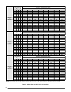
Selecting Minimum Electric Heat Airflow
The minimum electric heat airflow setting controls the
minimum air flow that will be produced whenever electric
heater kits are used. When the electric heater kit is
energized along with a heat pump, the airflow may be
higher depending on the basic cooling/heat-pump airflow
setting. The minimum electric heat airflow is selected by
the red blower wire on 3-speed models or setting switches
1,2,3 & 4 on HMG**X1E models. HCG**V1E models
automatically set the heating speed based on the amount
of installed heat. The remaining 3 HEAT switches have no
function. Switch settings are listed in Table 6 (page 20)
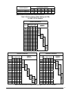
or Table 9 (page 22). NOTE: For HMG**X1E Models, the
minimum electric heat airflow setting may be set higher,
but must never be set lower than the setting shown in
Table 7 (page 21).