


Page 17
Yosemite Wood Stove
7004-187F September 1, 2008
R
Items Needed for Installation: 4 inch (102mm) diameter flex pipe in
the length as required for your installation; Phillips screwdriver; Silicone
sealant; Drills and saws necessary for cutting holes through the wall or
flooring in your home.
Included in Kit: 2 cable ties; oustide air termination cap; mounting
screws (Discard the remaining parts).
In Stove's Component Pack: Outside air cover plate
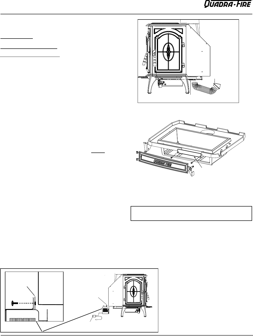
OUTSIDE AIR KIT INSTALLATION
Part 831-1780
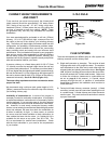
NOTE: If you plan to install the optional blower AND the
outside air kit, complete the installation of the
outside air kit FIRST.
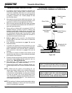
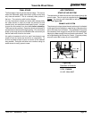
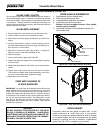
1. Remove 3 phillips head screws from rear of stove.
2. Using the phillips head screws, attach blower to lower rear of stove, as
shown.
3. Plug blower cord into a grounded outlet. Do not remove ground prong from
plug. Route power cord to avoid heat from the stove, or other damage.
Do not route cord under or in front of appliance.
4. Adjust the blower speed control to the desired speed.
INSTALLATION OF OPTIONAL BLOWER
Part 831-1701
The blower is shipped fully assembled
and ready for installation.
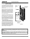
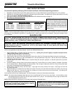
NOTE: When the speed control is turned
clockwise, it will click on to high speed. Turn
the speed control clockwise to decrease the
speed. At full clockwise, the blower should
blow gently, but should not stop.
1. With the stove plugged in, turn the speed
control knob to slow (full clockwise).
2. With a small screwdriver, adjust the blower
speed by turning the adjustment mechanism
through the hole on the side of the speed
control.
3. Adjust the speed so the blower runs slowly,
but does not stop. Turn clockwise to slow the
blower and counterclockwise to increase the
speed.
*The blower speed control for this unit is adjusted at the factory,
and normally does not require further adjustment.
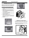
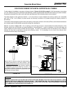
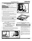
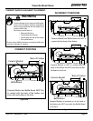
OUTSIDE AIR
TERMINATION CAP
(contains rodent screen)
OUTSIDE AIR
INTAKE
COVER PLATE
OUTSIDE AIR
COVER PLATE
Figure 17A
Figure 17B
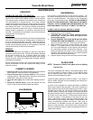
ADJUSTING THE BLOWER SPEED CONTROL
*If Necessary
Figure 17C
REAR SHIELD
BLOWER MOUNTING
FLANGE
BLOWER SPEED CONTROL
BLOWER
MOUNTING
FLANGE
REAR
SHIELD
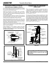
Remove all materials from packing box and stove component pack
.
1. Remove ash lip by using a 7/16” wrench and remove the 2 bolts
underneath the ash lip. Carefully lower and set aside.
2. Swing open ash removal door.
3. Remove 2 screws from the stove bottom. Place cover over the air
opening and secure with same 2 screws. Figure 17B.
4. Mount the flex flange (with pipe fitting extending out), over the intake
air opening at the rear of the stove using the four mounting screws
supplied with the kit. Figure 17A.
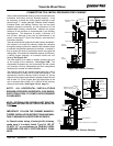
Cut a 4 inch (102mm) minimum hole in the floor or wall to accommo-
date outside air piping. Use 4 inch (102mm) metal flex or rigid piping
to directly connect outside air to the unit or into vented crawl space.
(Do not put flex into a non-vented crawl space).
If using flex tubing attach cable ties to secure tubing at both ends. Use
the supplied termination cap with a rodent screen. Seal between the floor
or wall and the pipe with silicone to prevent moisture penetration.