


Page 15
Yosemite Wood Stove
7004-187F September 1, 2008
R
When a metal prefabricated chimney is used, the manufacturer’s
installation instructions must be followed precisely. It will
be necessary to install the ceiling support package or wall
pass through, “T” section package, firestops (when needed),
insulation shield, roof flashing, chimney cap, and any other
materials deemed necessary by the instructions of the
prefabricated chimney manufacturer. Maintain the proper
clearance to the structure as recommended by the chimney
manufacturer. This clearance is usually a minimum of 2
inch (51mm), although it may vary by manufacturer or for
certain components. Follow the chimeny manufacturers’
instructions carefully.
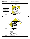
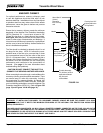
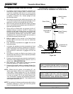
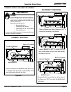
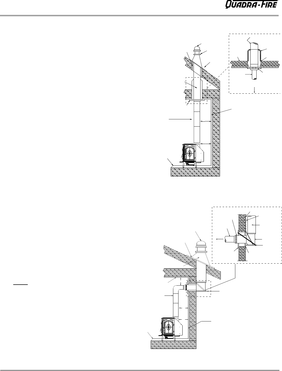
There are basically two methods of metal chimney installation.
One method is to install the chimney inside the residence
through the ceiling and the roof. Install an attic insulation shield
to maintain the specified clearance to insulation. Insulation in
this air space will cause a heat buildup which may ignite the
ceiling joists. This method of installation requires, at minimum,
a ceiling support package, an insulation shield and roof
flashing. See Figure 15A.
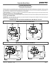
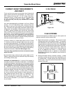
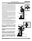
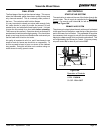
The other method is to install an exterior chimney that runs
up the outside of the residence. See Figure 15B. The
components illustrated may not look exactly like the system
you purchase, but they demonstrate the basic components
necessary for a proper and safe installation.
The chimney must be the required height above the roof or
other obstruction for safety and for proper draft operation. The
requirement is that the chimney must be at least 3 ft. (91cm)
higher than the highest point where it passes through the roof
and at least 2 ft. (61cm) higher than the highest part of the
roof or structure that is within 10 ft. (305cm) of the chimney,
measured horizontally. (See Figure 11A on page 11)
In Canada when using a factory-built chimney,
make sure it is safety listed, Type UL 103 HT
CLASS "A" or conforming to CAN/ULC-S629,
STANDARD FOR 650°C FACTORY-BUILT CHIM-
NEYS.
CONNECTION TO A METAL PREFABRICATED CHIMNEY
IMPORTANT! FOLLOW THE CHIMNEY MANUFAC-
TURERS’ INSTALLATION INSTRUCTIONS AND MAIN-
TAIN CLEARANCES AS SPECIFIED ON PAGE 6.
Floor
Protector
Chimney
Connector
Combustible
Ceiling
Combustible Wall
Insulated "T"
Flashing
Listed Cap
Maintain 2" (51mm)
Clearance Through Eave
*
*
*
Listed
Chimney Pipe
Chimney
Connector
To Stove
Trim Collar
on Inside
Wall
Combustible Outside Wall
2" (51mm)
Clearance
Listed Chimney
Insulated "T"
Wall Support
Wall Spacer on
Outside Wall
*Refer to Clearances to Combustibles
Combustible Wall
Floor
Protector
Chimney
Connector
Ceiling Support
Listed Chimney
Maintain 2" (51mm)
Clearance
Listed Cap
Storm Collar
Flashing
*
*
*Refer to Clearances
to Combustibles
Combustible
Ceiling
Joists
Chimney
Connector
To Stove
Ceiling
Support
Specified
Clearanc
e
Attic
Insulation
Shield
Listed
Chimney
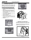
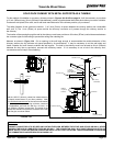
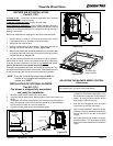
NOTE: ALL HORIZONTAL INSTALLATIONS
REQUIRE ACCESSORY HORIZONTAL FLUE SHIELD,
PART HTSHLD-7006, TO COMPLY WITH REQUIRED
CLEARANCES.
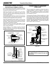
NOTE: OPTIONAL FIRE SCREEN, PART SCR-7006,
CAN ONLY BE USED IN FULL VERTICAL INSTALLA-
TIONS.
Figure 14B - Exterior Chimney
Figure 14A - Interior Chimney