


Page 11
Yosemite Wood Stove
7004-187F September 1, 2008
R
To be sure that your stove burns properly, the chimney draft
(static pressure) should be approximately -.04” water column
(W.C.) during a low burn and -.10” W.C. during a high burn,
measured 6 inches” (152mm) above the top of the stove after
one hour of operation at each burn setting.
NOTE: These
are guidelines only, and may vary somewhat for individual
installations.
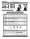
Your stove was designed for and tested on a 6 inch (152mm)
chimney, 12 ft-14 ft (360-420cm) high, measured from the
flue collar to the top of the chimney (not including chimney
cap). The further your stack height or diameter varies from this
configuration, the possibility of performance problems exists.
In addition, exterior conditions such as roof line, surrounding
trees, prevailing winds and nearby hills can influence stove
performance. Your local dealer is the expert in your geographic
area and can usually make suggestions or discover solutions
that will easily correct your flue draft problem, allowing your
woodstove and its flue system to operate correctly and provide
safe and economical heat for your home.
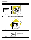
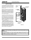
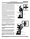
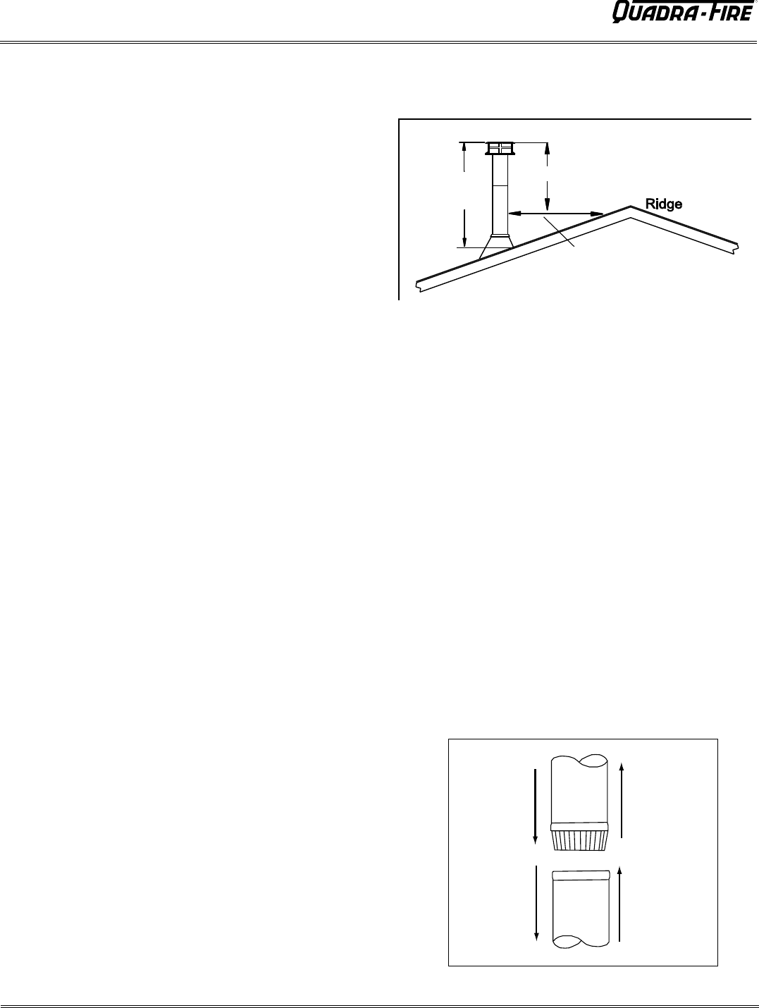
A masonry chimney or a listed factory-built UL103 HT Class
“A” chimney must be the required height above the roof and
any other nearby obstructions. The chimney must be at least 3
ft. (91cm) higher than the highest point where it passes through
the roof and at least 2 ft. (61cm) higher than the highest part of
the roof or structure that is within 10 ft. (305cm) of the chimney,
measured horizontally. See 2-10-3 Rule (Figure 11A)
These are safety requirements and are not meant to assure
proper flue draft.
We recommend using a minimum total system height of 12 ft.
(360cm), measured from the flue collar to the top of the chimney
(not including chimney cap).
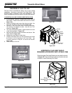
Availability of combustion air: A source of air (oxygen) is
necessary in order for combustion to take place. It is important
to realize that whatever combustion air is consumed by the fire
must be replaced. If you are using room air, the air is replaced
via air leakage that occurs around windows and under doors,
etc. However, in most newly constructed houses, mobile
homes, or even existing homes that are fitted with tightly sealed
doors and windows, the area from which the combustion air
is taken is relatively air tight. In these cases, an outside
air source must be made available to feed combustion air
from outside the home into the stove. An Outside Air Kit is
available for this stove as an option, Part 831-1780. The
kit is a requirement for mobile home installations. Check
with the local authorities in your area for the requirements
in your location.
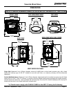
CHIMNEY HEIGHT REQUIREMENTS
AND DRAFT
3 ft Min
(91cm)
2 ft Min (61cm)
10 ft Min
(305cm)
2-10-3 RULE
Figure 11A
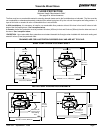
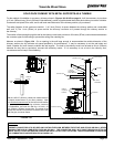
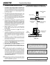
FLUE SYSTEMS
There are two separate and different parts to a flue system: the
chimney connector and the chimney itself.
A. Single wall connector or stovepipe. This must be at least
24 gauge mild steel or 26 gauge blue steel. The sections
must be attached to the stove and to each other with the
crimped (male) end pointing toward the stove. See Figure
11B. All joints, including the connection at the stove collar,
should be secured with 3 sheet metal screws. Make sure
to follow the minimum clearances to combustibles as
set out on page 6 of this manual. In Canada, where
passage through the wall, or partition of combustible
construction is desired, the installation shall conform to
CAN/CSA-B365.
B.
Factory-built listed chimney connector (vented). A listed
connector (vented) must be used when installing this unit
in a mobile home. A Listed chimney and Listed connector
must be used. They must conform to each other to ensure
a proper fit and seal.
FLUE
GAS
DIRECTION
TOWARDS
STOVE
Figure 11B -Chimney Connector
2-10-3 RULE