


Heat & Glo • SL-750TRS-IPI-E, SL-550TRS-IPI-E, SL-350TRS-D, SL-350TRS-IPI • 2120-900 Rev. D • 6/07 49
12
12
Appliance Setup
A. Remove Shipping Materials
Remove shipping materials from inside or underneath the
fi rebox.
B. Clean the Appliance
Clean/vacuum any sawdust that may have accumulated
inside the fi rebox or underneath in the control cavity.
C. Accessories
Install only approved accessories per instructions included
with accessories. See your dealer or visit www.heatnglo.
com for appropriate accessories.
Shock or fi re risk.
Use ONLY optional accessories approved for
this appliance.
• Using non-listed accessories voids warranty.
• Using non-listed accessories may result in a
safety hazard.
• Only Hearth & Home Technologies approved
accessories may be used safely.
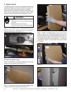
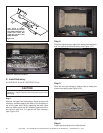
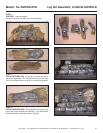
D. Lava Rock, Mineral Wool/Ember Placement
Placing the Lava Rock (SL-350TRS-D only)
See Section 12F for Lava Rock placement instructions.
Explosion Risk.
• Follow ember placement instructions in manual.
• Do NOT place embers directly over burner ports.
• Replace ember material annually.
Improperly placed embers interferes with proper burner
operation.
WARNING
WARNING
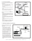
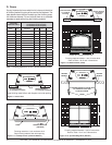
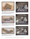
Figure 12.3 Placement of Embers
EMBER MATERIAL
Placing the Ember Material
Ember material is shipped with this gas appliance. To place
the ember material:
• Embers CANNOT be placed directly over ports. See
Figure 12.4 for the only exception to this guideline. Care
should be taken not to cover the lighting trail of ports
(from back to front).
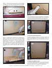
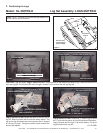
• When placing Glowing Embers
®
onto the burner care should
be taken so that the ports are not covered. Place the dime-
size ember pieces near the port holes in the burner top (see
Figure 12.3 and 12.5). Failure to follow this procedure will
likely cause lighting and sooting problems.
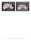
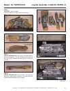
• Place Mytic Embers on areas of base refractory away from
port holes. Use this material to give the appliance a realistic
ash bed (SL-550TRS-IPI-E and SL-750TRS-IPI-E only).
• Save the remaining ember materials for use during appli-
ance servicing. The embers provided should be enough
for 3 to 5 applications.
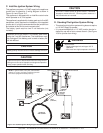
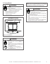
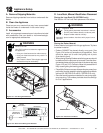
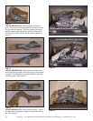
RHEOSTAT
SWITCH
TEMPERATURE
SENSOR
BLUE
VARIABLE
SPEED SWITCH
TEMPERATURE
SENSOR SWITCH
JUNCTION BOX
Figure 12.1 Fan Wiring with Rheostat
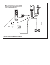
Figure 12.2 Detail of Fan Wiring with Rheostat