


Heat & Glo • SL-750TRS-IPI-E, SL-550TRS-IPI-E, SL-350TRS-D, SL-350TRS-IPI • 2120-900 Rev. D • 6/07 27
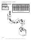
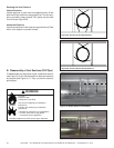
2 SCREWS
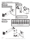
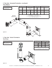
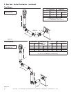
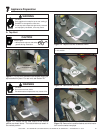
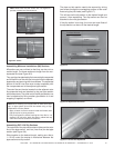
A. Top Vent
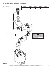
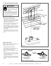
Figure 7.4 Remove the vent cap.
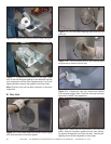
Figure 7.5 Remove the insulation basket and white insula-
tion from the center vent pipe.
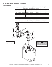
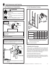
Figure 7.1 For top vent, remove the two screws holding the
top heat shield in place. For rear vent, see Section 7B.
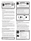
CAUTION
Sharp Edges
• Wear protective gloves and safety
glasses during installation.
Note: Actual unit may look different than the fi replace shown
in this section.
7
7
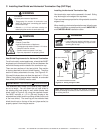
Appliance Preparation
2 SCREWS
Figure 7.3 Replace the two screws as shown.
Fire Risk
Do not remove heat shield.
Elevated header temperatures may cause a fi re.
WARNING
WARNING
Fire Risk
Once appliance is setup for top or rear venting, it
CANNOT be changed at a later time.
If vent cap and components previously removed
are improperly reinstalled, a fi re may result.
Figure 7.2 Rotate the top heat shield to the vertical
position as shown above. The heat shield must remain in
the vertical position.