


Heat & Glo • PIER-HVB-IPI, ST-HVB-IPI • 2006-901 Rev. C • 12/07
34
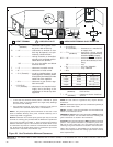
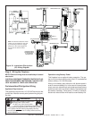
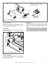
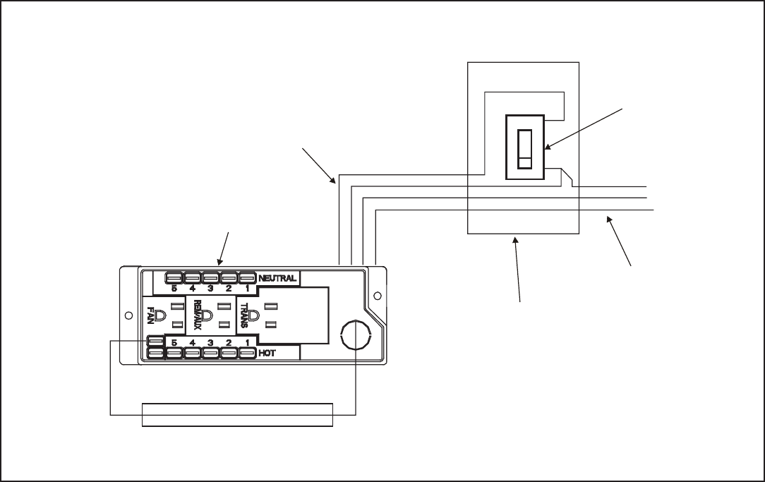
If the box is being wired to a wall mounted switch for use
with a fan (See Figure 37):
• The power supply for the appliance must be brought into
a switch box.
• The power can then be supplied from the switch box to
the appliance using a minimum of 14-3 with ground wire.
• At the switch box connect the black (hot) wire and red
(switch leg) wire to the wall switch as shown.
• At the appliance connect the black (hot), white (neutral)
and green (ground) wires to the junction box as shown.
• Add a 1/4 inch insulated female connector to the red
(switch leg) wire, route it through the knockout in the
face of the junction box, and connect to the top fan switch
connector (1/4 inch male) as shown.
Figure 37. Junction Box Wired to Wall Switch
Wall Switch Installation for Fan (Optional)
Red
Red
BlackBlack
Green
Green
White
White
Red
Black
Green
White
SWITCH BOX
JUNCTION BOX
POWER
SUPPLY WIRES
SWITCH
MINIMUM 14-3 AWG
WITH GROUND
Use to manually control fan with wall switch.