


Heat & Glo • PIER-HVB-IPI, ST-HVB-IPI • 2006-901 Rev. C • 12/07
32
IGNITION
MODULE
(3V)
VALVE
LOW VOLTAGE
PLUG-IN
3V TRANSFORMER
NEUTRAL
HOT
GROUND
FLAME SPARKER/
SENSOR
REMOTE
CONTROL
SEE NOTE 1
IGNITION MODULE 3 VAC
INTERMITTENT
PILOT IGNITOR
GROUND TO
FIREPLACE
CHASSIS
VALVE
TRANSFORMER
3 VAC
ORG
WHT
ORG
GRN
WHT
ON/OFF
WALL SWITCH
BRN
BRN
BLK
WHT
BLK
WHT
BLK
WHT
BLK
TERMINAL BLOCK
BULB SOCKET
ASSEMBLY (3)
FLAME ON/OFF
PLUG IN
BLACK WIRE CAN BE
PLUGGED INTO ANY OF
#1 - #5 LOCATIONS
ON THE HOT SIDE
WHITE WIRE
CAN BE
PLUGGED
INTO ANY
OF #1 - #5
LOCATIONS
ON THE
NEUTRAL
SIDE
SCALE 1/1
S
I
ELECTRONIC EMBERS
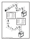
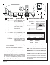
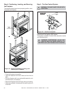
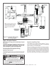
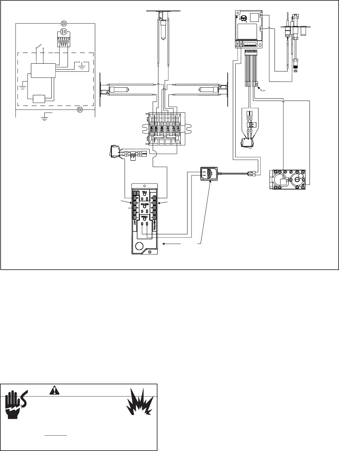
Step 8. Wiring the Fireplace
NOTE: Electrical wiring must be installed by a licensed
electrician.
CAUTION: DISCONNECT REMOTE CONTROLS IF AB-
SENT FOR EXTENDED TIME PERIODS. THIS WILL PRE-
VENT ACCIDENTAL FIREPLACE OPERATION.
For Intermittent Pilot Ignition Wiring
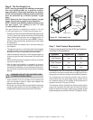
Appliance Requirements
This appliance requires that 110-120 VAC be wired to the
junction box. Maintain correct polarity when wiring the junc-
tion box.
Figure 34. Intermittent Pilot Ignition
(IPI) Wiring Diagram
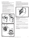
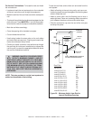
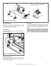
Operation using Battery Power
This fireplace has an optional battery operation. The sys-
tem is fully functional with the use of two “D” size batteries
without ordinary 110-120 VAC power.
Wiring to the battery pack should be left disconnected in
order to conserve battery life. In the case of a loss of power,
simply connect red and black wire leads to activate battery
power (connect red to red, black to black). The fireplace can
be used as necessary. Once power (110 VAC) is restored,
disconnect red and black wire leads to extend battery life.
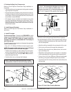
Note: An alternate electronic ember
switch can be installed on the wall
by connecting a minimum 18 gage
Romex™ to the leads supplied on
the back of the electric ember
switch.
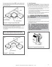
WARNING
Wire 110V to electrical junction box.
Do NOT wire 110V to valve.
Do NOT wire 110V to wall switch.
• Incorrect wiring will damage millivolt valves.
• Uninterrupted or continuous power is required at all times
in IPI system
EXCEPT when using battery back-up.
• Incorrect wiring will override IPI safety lockout and may
cause explosion.