


Heat & Glo • PIER-HVB-IPI, ST-HVB-IPI • 2006-901 Rev. C • 12/07
26
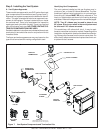
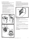
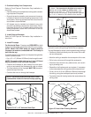
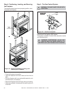
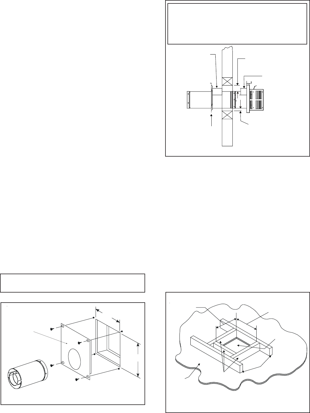
4. Install Firestops
For Horizontal Runs - Firestops are REQUIRED on both
sides of a combustible wall through which the vent passes.
NOTE: Model DVP-TRAP does not need an exterior
firestop on an exterior combustible wall. The firestop is
built into the cap.
To install firestops for horizontal runs that pass through either
interior or exterior walls:
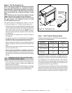
• Cut a 10” x 12” (254mm X 305mm) hole through the wall.
NOTE: The center of the hole is one (1) inch (25.4mm)
above the center of the horizontal vent pipe.
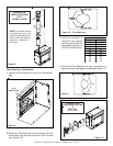
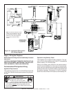
• Position the firestops on both sides of the hole previ-
ously cut and secure the firestops with nails or screws.
• The heat shields of the firestops MUST BE placed to-
wards the top of the hole.
• Continue the vent run through the firestops.
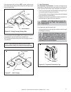
Figure 23. 10" x 12" Hole and Vent Pipe
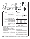
3. Install Support Brackets
Refer to Cinch Pipe and Termination Cap installation in-
structions.
2. Continue Adding Vent Components
Refer to Cinch Pipe and Termination Cap installation in-
structions.
• Continue adding vent components, locking each succeed-
ing component into place.
• Ensure that each succeeding vent component is secure-
ly fitted and locked into the preceding component in the
vent system. Securing pipe sections with a maximum of
two screws is recommended.
• 90° elbows may be installed and rotated to any point
around the preceding component’s vertical axis. If an el-
bow does not end up in a locked position with the pre-
ceding component, attach with a minimum of two (2)
sheet metal screws.
NOTE: There must be NO INSULATION or other
combustibles inside the framed firestop opening.
10"
12"
INTERIOR
WALL SHIELD
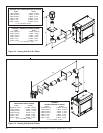
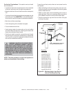
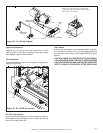
For Vertical Runs - One ceiling firestop is REQUIRED at
the hole in each ceiling through which the vent passes.
To install firestops for vertical runs that pass through ceilings:
• Position a plumb bob directly over the center of the verti-
cal vent component.
• Mark the ceiling to establish the centerpoint of the vent.
• Drill a hole or drive a nail through this centerpoint.
• Check the floor above for any obstructions, such as wir-
ing or plumbing runs.
• Reposition the fireplace and vent system, if necessary,
to accommodate the ceiling joists and/or obstructions.
• Cut an 10-inch X 10-inch (254mm x 254mm) hole through
the ceiling, using the centerpoint previously marked.
• Frame the hole with framing lumber the same size as the
ceiling joists.
Figure 25 Hole & New Framing Members
CEILING
NEW
FRAMING
MEMBERS
EXISTING CEILING
JOISTS
CHIMNEY
HOLE
10" (254mm)
10" (254mm)
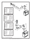
HEAT
SHIELD
HEAT
SHIELD
1 in. CLEARANCE
BOTTOM & SIDES
WALL
WALL
SHIELD
FIRESTOP
3 in. TOP
CLEARANCE
Note: Heat shields MUST overlap by a minimum of 1-1/2
in. (38mm). The heat shield is designed to be used on a
wall 4 in. to 7-1/4 in. (102mm to 184mm) thick. If wall
thickness is less than 4 in. (102mm) the existing heat
shields must be field trimmed. If wall thickness is greater
than 7-1/4 in. (184mm) a DVP-HSM-B will be required.