


Heat & Glo • PIER-HVB-IPI, ST-HVB-IPI • 2006-901 Rev. C • 12/07
33
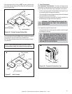
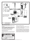
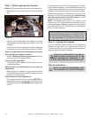
Wall Switch
Position the wall switch in the desired position on a wall.
Run a maximum of 25 feet (7.8 m) or less length of 18 A.W.G.
minimum wire and connect it to the fireplace ON/OFF switch
pigtails.
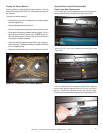
CAUTION: LABEL ALL WIRES PRIOR TO DISCONNEC-
TION WHEN SERVICING CONTROLS. WIRING ERRORS
CAN CAUSE IMPROPER AND DANGEROUS OPERATION.
VERIFY PROPER OPERATION AFTER SERVICING.
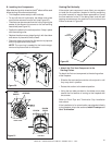
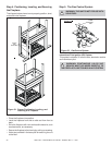
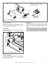
Fan Installation
Recommended fan locations for the type of fireplace you
have (see Figure 36).
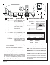
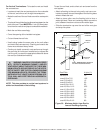
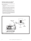
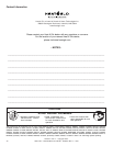
Figure 35. Fan Wiring Diagram
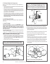
Optional Accessories
Optional fan and remote control kits require that 110-120
VAC be wired to the factory installed junction box before
the fireplace is permanently installed.
NOTE: If any of the original wire as supplied with
the appliance must be replaced, it must be replaced
with the type 105
o
C rated wire.
FAN
JUNCTION
BOX
SPEED CONTROL
(RHEOSTAT)
TEMPERATURE
SENSOR SWITCH
SEE DETAIL A
DETAIL A
SCALE 1/1
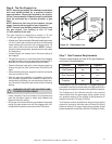
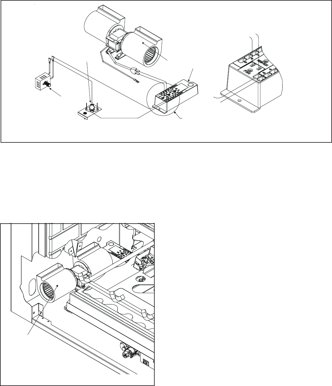
Figure 36. ST & PIER fan location
FAN
ST & Pier fan location
It is recommended to position the fan on the same side of
the fireplace as the vent collars are on. This will provide the
best air flow (see Figure 36).