


Heat & Glo • PIER-HVB-IPI, ST-HVB-IPI • 2006-901 Rev. C • 12/07
25
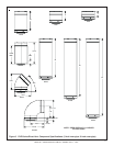
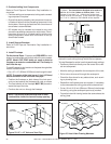
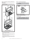
1. Attach the First Vent Component to the
Starting Collars
To attach the first vent component to the starting collars
of the fireplace:
• Slide the first vent section onto the unit and push in until
they snap lock in position.
• Rotate this section to the desired position.
• Using the two tabs provided on the elbow cover plate,
secure the first section of venting to the fireplace with
two screws.
Refer to Cinch Pipe and Termination Cap installation
instructions.
If the installation is for a termination cap attached directly
to the fireplace, skip to the sections, Install Firestops and
Vent Termination.
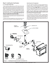
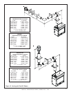
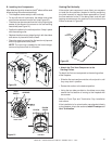
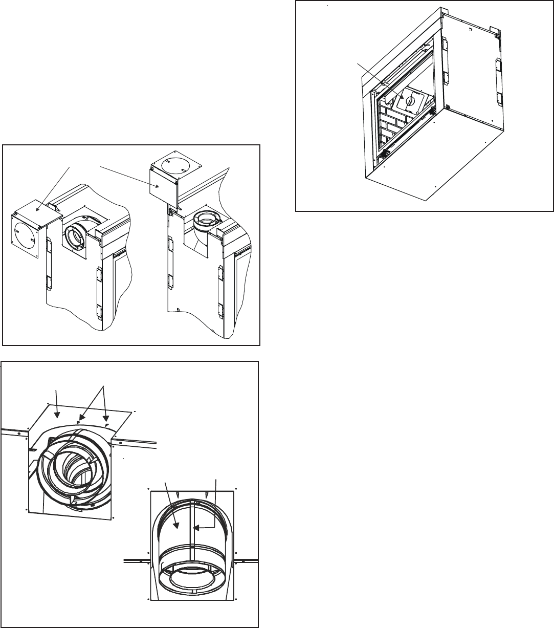
B. Installing Vent Components
After determining which direction the 45
O
elbow will be used
follow venting instructions accordingly.
• This fireplace comes ready to vent vertically.
• To vent off the unit horizontally, the elbow cover plate
must first be removed from the unit (see Figure 20).
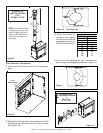
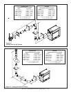
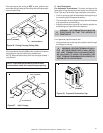
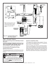
• The elbow can be removed from the unit by aligning the
seams of the elbow to the arrows on the surrounding
heat shield (see Figure 21).
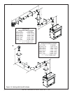
• Position the elbow in the vertical position. Snap in place
with the starting collar.
• Replace the elbow cover plate aligning it with the elbow
and secure in place with the 8 screws.
• Place the rope ring around the first section of pipe and
slide it up against the cover plate.
NOTE: The rope ring is needed for the heat manage-
ment and to prevent cold air infiltration.
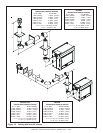
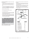
Venting Out Vertically
If the vertical vent component is over 4 feet, you may want
to install the flue restrictor (located in the bag containing
the install manual) to improve flame appearance. Center
the flue restrictor on the 5” flue being used, and with self
tapping screws secure the restrictor to the inside of the
firebox as shown in Figure 22.
Figure 20
Figure 22
FLUE
RESTRICTOR
ELBOW COVER PLATE
Figure 21
TOP VIEW
HEAT
SHIELD
ARROWS
ELBOW
ELBOW
SEAM
FRONT VIEW