


Heat & Glo • PIER-HVB-IPI, ST-HVB-IPI • 2006-901 Rev. C • 12/07
19
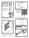
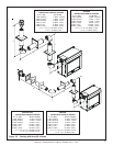
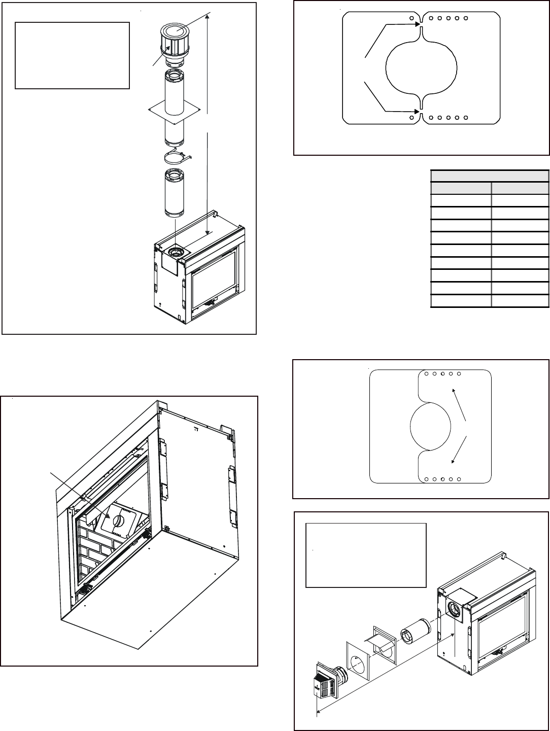
Figure 8
NOTE: On vertical venting
configurations you may
want to install the flue re-
strictor (385-128). See flue
restrictor installation in-
structions.
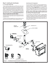
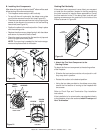
Flue Restrictor Instructions
1. Locate the Flue Restrictor which is in the manual
bag.
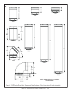
Figure 10. Flue Restrictor
BREAK
HERE
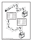
Figure 9
2. Break the Flue Restrictor into two pieces. Do this
by bending the part back and forth until it breaks
(see Figure 10).
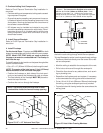
1 2 3 4 5
SETTINGS
1 2 3 4 5
4. Center the Flue Restrictor on vent and secure in
place using two self-tapping screws (see Figure 11).
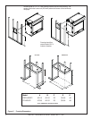
STRAIGHT OUT
HORIZONTAL VENTING
H
Max. Run
24" (610 mm)
Figure 12.
V
CAP
H
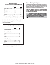
3. Match the amount of
vertical in the system
with the chart to find the
appropriate position to
set the Flue Restrictor.
Figure 11
- CHART -
Vertical Settings
4' 1-1
8' 1-2
15' 2-2
20' 2-3
25' 3-3
30' 4-3
35' 4-4
40' 4-4
50' 4-5
FLUE
RESTRICTOR
STRAIGHT UP
VERTICAL VENTING
V (FT.)
50' MAX. (15.2 M)