


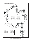
9
Heat & Glo • 6000TRSI-AUC • 2078-900 Rev. G • 12/06
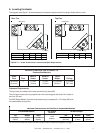
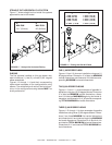
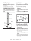
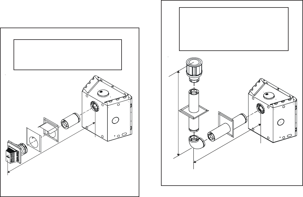
FIGURE 1.7 Straight Out Horizontal Flueing
HH
MIN. RUN MAX. RUN
13.1" (331mm) 24" (610mm)
H
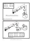
FIGURE 1.8 Flueing with One 90° Elbow
V H
1´ MIN. (0.30 M) 2´ MAX. (0.61 M)
2´ MIN. (0.61 M) 4´ MAX. (1.22 M)
3´ MIN. (0.91 M) 6´ MAX. (1.83 M)
4´ MIN. (1.22 M) 8´ MAX. (2.44 M)
24´ MAX. (7.32 M) 8´ MAX. (2.44 M)
V
H
STRAIGHT OUT HORIZONTAL FLUE SYSTEM
Figure 1.7 shows straight out horizontal flue systems
approved for use on this model.
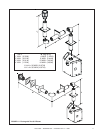
ONE (1) 90-DEGREE ELBOW
Figures 1.8 and 1.9 show an installation using one (1)
90-degree elbow. Dimension V is listed as MINIMUM
vertical dimensions and dimension H is listed as corre-
sponding MAXIMUM horizontal dimensions.
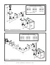
TWO (2) 90-DEGREE ELBOWS
Figures 1.10 and 1.11 show examples of possible in-
stallations using two (2) 90-degree elbows. Dimension
V is listed as MINIMUM vertical dimensions, dimen-
sion H is listed as MAXIMUM beginning horizontal di-
mensions, and dimension H+H
1
is listed as correspond-
ing TOTAL MAXIMUM horizontal dimensions.
THREE (3) 90-DEGREE ELBOWS
Figures 1.12 through 1.14 show examples of possible
installations using three (3) 90-degree elbows. Dimen-
sions V are listed MINIMUM first vertical dimensions
and dimensions H are listed as beginning MAXIMUM
horizontal dimensions. Dimensions H+H
1
and
H+H
1
+H
2
are listed as TOTAL MAXIMUM horizontal dimensions.
Dimensions V+V
1
are listed as TOTAL MAXIMUM ver-
tical dimensions.
ELBOWS
The flue systems installed on this gas heater may
also include one (1), two (2), or three (3) 90 - degree
elbow assemblies.
Figures 1.8 through 1.14 and their corresponding
tables show examples of flue configurations using
elbows. The relationships of vertical rise to horizon-
tal run in flue configurations using elbows MUST be
strictly adhered to.