


8
Heat & Glo • 6000TRSI-AUC • 2078-900 Rev. G • 12/06
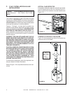
This model is approved to use DVP-Series flue pipe
components. A DVP-TRAP2 Termination Cap must be
used to terminate flue systems in a horizontal position.
A DVP-TVHW vertical Termination Cap must be used to
terminate flue systems in a vertical position.
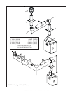
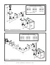
Figures 1.7 through 1.14 show the flue systems ap-
proved for these models. Approved flue system compo-
nents are labeled for identification. NO OTHER FLUE
SYSTEMS OR COMPONENTS MAY BE USED. De-
tailed installation instructions are included with each
flue termination kit and should be used in conjunction
with this manual.
WARNING: THIS GAS APPLIANCE AND FLUE AS-
SEMBLY MUST BE FLUED DIRECTLY TO THE OUT-
SIDE AND MUST NEVER BE ATTACHED TO A CHIM-
NEY SERVING A SEPARATE SOLID FUEL BURNING
APPLIANCE. EACH GAS APPLIANCE MUST USE A
SEPARATE FLUE SYSTEM-COMMON FLUE SYS-
TEMS ARE PROHIBITED.
CAUTION: UNDER NO CONDITION SHOULD COM-
BUSTIBLE MATERIAL BE CLOSER THAN 3 INCHES
(2 1/2 INCHES AT WALL FIRESTOPS) FROM THE
TOP OF THE 8 INCH PIPE OR 1- INCH TO THE SIDES
AND THE BOTTOM FOR HORIZONTAL SECTIONS
OF THIS FLUE SYSTEM. VERTICAL SECTIONS OF
THIS SYSTEM REQUIRE A MINIMUM OF 1 INCH
CLEARANCE TO COMBUSTIBLE MATERIALS ALL
AROUND THE 8 INCH PIPE.
For alternative installations, other than depicted, con-
tact your dealer for further information.
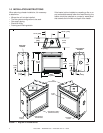
Refer to Figure 1.4 for required clearances to flue ter-
minals.
MODEL FLUE TERMINATION APPROVALS
6000TRSI-AUC DVP-TRAP2, DVP-TVHW
TABLE 1
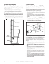
FIGURE 1.5
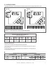
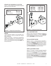
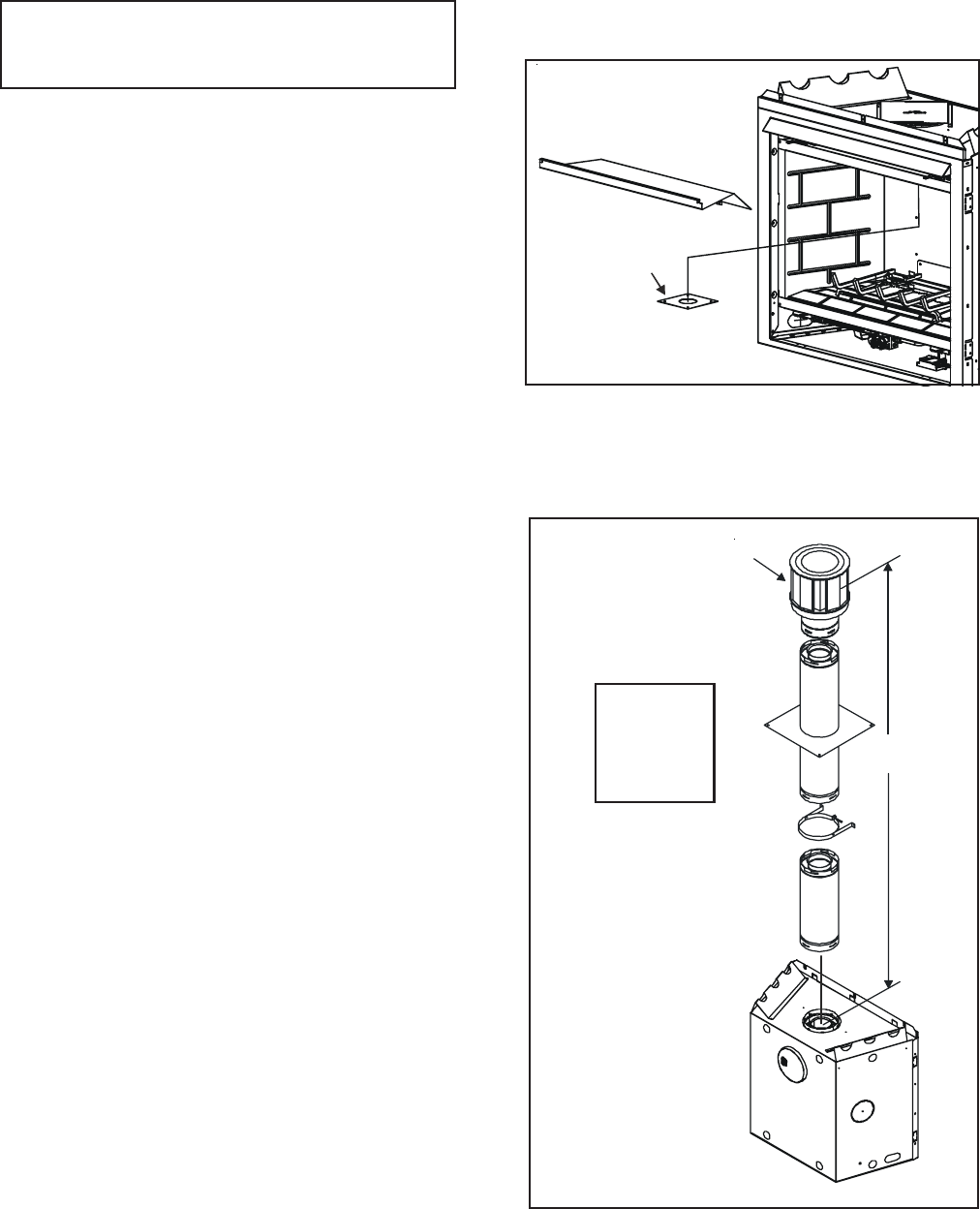
VERTICAL FLUE RESTRICTOR
If the heater installation requires a vertical flue exceed-
ing 4.5m above the unit with no horizontal flue or el-
bows a vertical flue restrictor must be installed (see
Figure 1.5).
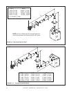
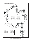
FIGURE 1.6
V
CAP
V
MAX. RUN
36 FT.
(10.97m)
STRAIGHT UP VERTICAL FLUE SYSTEM
Figure 1.6 shows straight up vertical flue system ap-
proved for use on this model.
C. FLUE SYSTEM APPROVALS AND
INSTALLATIONS
RESTRICTOR
PLATE