


5
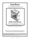
Heat & Glo • 6000TRSI-AUC • 2078-900 Rev. G • 12/06
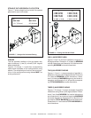
Clearance Requirements
The top, back, and sides of the heater are defined by standoffs.
The minimum clearance to a perpendicular wall extending past the face of the heater is
one inch (25 mm).
For 6000 Series Models, the back of the heater may be recessed 21-1/2 inches (546 mm)
into combustible construction.
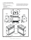
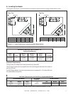
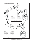
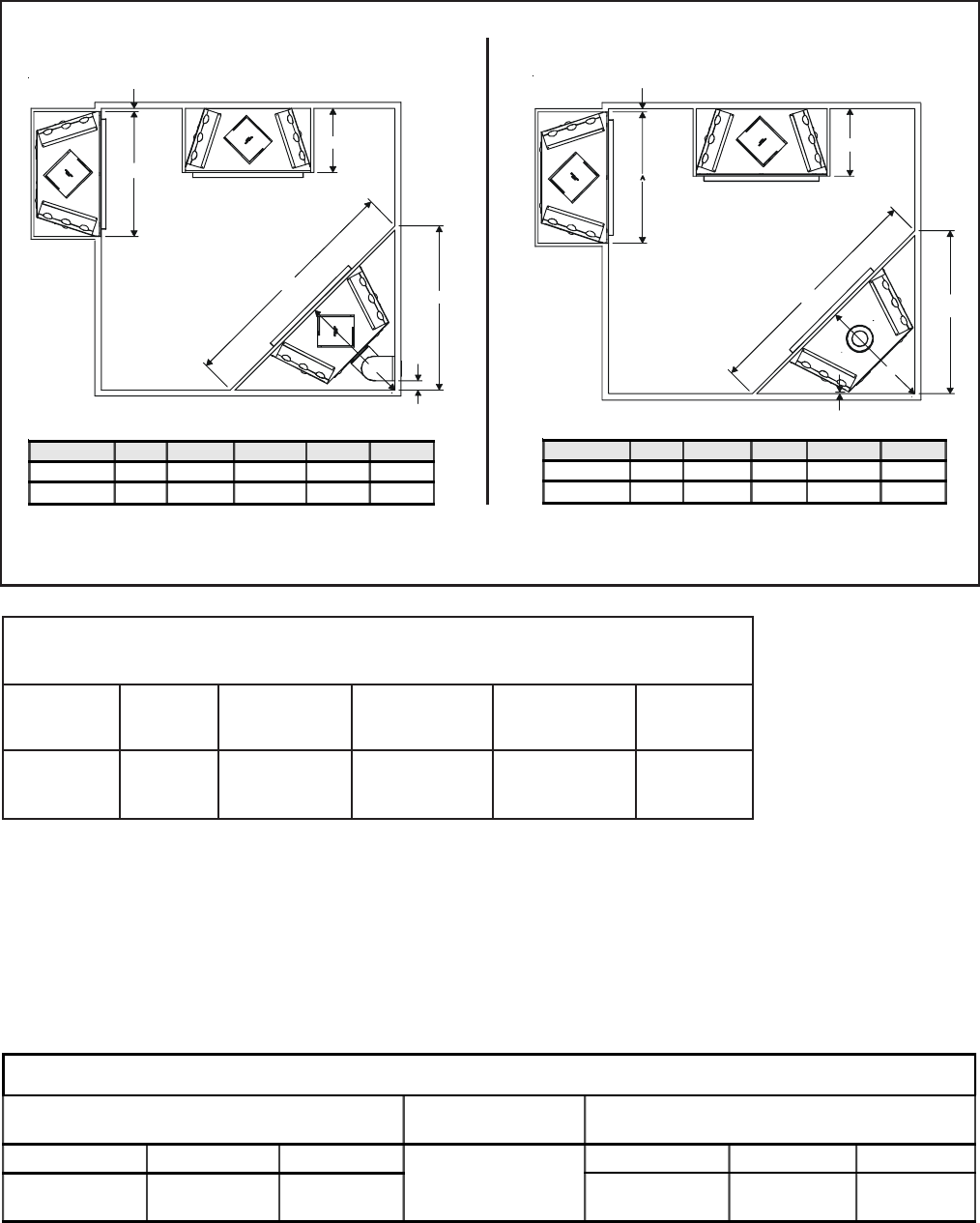
FIGURE 1.2 Heater Dimensions, Locations and Space Requirements
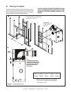
A. Locating the Heater
The diagram (see Figure 1.2) shows space and clearance requirements for locating a heater within a room.
Minimum Clearances from the Heater to
Combustible Materials
Glass Back of Sides of Top of
Front Floor Heater Heater Heater Ceiling
36 inches 0 1/2 inch 1/2 inch 3-1/2 inches 31 inches
(914 mm) (13 mm) (13 mm) (89 mm) (787 mm)
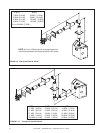
1”MIN. (25mm)
C
A
B
D
E
3” (76.2mm)
A B C D E
Inches 42
22 38 53-3/4 76
Millimeters 1066
559 965 1365 1930
Rear Flue
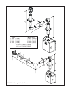
A B C D E
Inches 42
22 36 50-15/16 72
Millimeters
1066 559 914 1294 1829
1” MIN. (25mm)
B
E
1/2” MIN. (12.5mm)
C
D
Top Flue
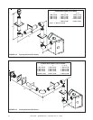
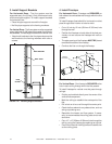
For minimum clearances, see the direct flue termination clearance diagrams on page 7.
Minimum Clearances from the Flue Pipe to Combustible Materials
For Horizontal Sections
For Vertical
Sections
At Wall Firestops
Top Bottom Sides
1 inch
(25mm)
Top Bottom Sides
3 inches
(75mm)
1 inch
(25mm)
1 inch
(25mm)
2-1/2 inches
(63.7mm)
1/2 inch
(13mm)
1 inch
(25mm)