


29
Heat & Glo • 6000TRSI-AUC • 2078-900 Rev. G • 12/06
A. REMOVAL OF COVERS FOR
SERVICING
A.Control Compartment Access Door
• Lift the lower door up and out to access the gas con-
trols.
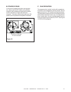
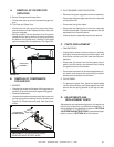
B.Trim Door and Glass Door
• Lift the front trim door up and out away from the ap-
pliance side surrounds. Replace the door when ser-
vicing is complete.
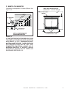
• Noting carefully how the brackets fit on the glass,
release the two spring latches at the top and two at
the bottom of the glass door. Carefully lift the glass
up and out away from the appliance. See Figure 3.2.
FIGURE 3.2
GLASS DOOR
ASSEMBLY
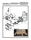
B. REMOVAL OF COMPONENTS
FOR SERVICE
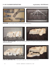
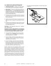
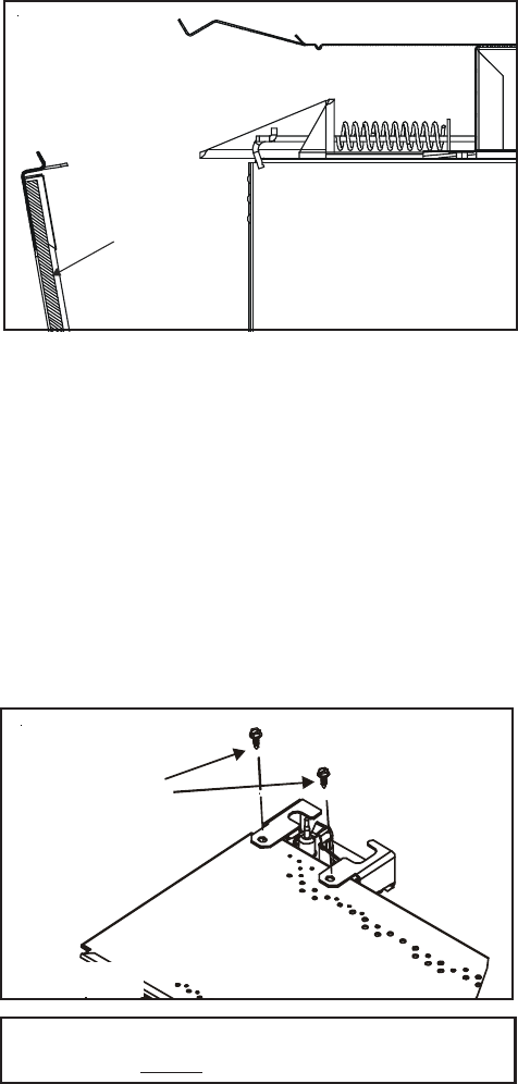
1. BURNER
• Release the screws at the base of the log grate and
carefully lift up and remove the logs and log grate.
• Remove the base pan.
• Unscrew the brackets at both ends of the burner and
the top two screws locating the pilot bracket (see
Figure 3.3). Slide the burner away from the burner
orifice.
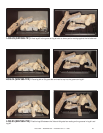
2. PILOT ASSEMBLY/IGNITION SYSTEM
• Remove the log set, log grate and burner assembly.
• Disconnect the gas supply tube from the underside
of the pilot burner.
• Disconnect the ignition cable.
• Disconnect the attachment nut from the underside
of the thermocouple. The thermocouple can then be
separated from the pilot bracket.
• Unscrew the pilot assembly bracket and remove.
C. PARTS REPLACEMENT
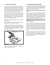
1. FAN/SWITCHES
• Unplug the fan wires from the junction box wires by
pulling the male and female connectors apart and
slide the fan out the front of the lower controls com-
partment.
• Disconnect the wires from the fan speed control
switch, pull off the knob, and remove the nut holding
the speed control to the bracket.
• Disconnect the wires from the fan temperature sen-
sor switch and remove the nut holding the switch
bracket onto the bottom of the firebox.
2. GLASS PANEL
• To replace the glass door, place the bottom edge
into the lower holders, push glass against unit and
secure the two spring latches at the top and bot-
tom.
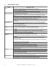
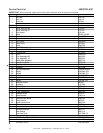
D. ADJUSTMENTS AND
REPLACEMENT PARTS
Adjustments and replacement parts for this appliance
should only be done by a qualified service person. A
wiring diagram for the appliance is shown in SECTION
2.0 OPERATING INSTRUCTIONS. A replacement part
table is shown in SECTION 4.0 of this manual.
PILOT BRACKET
RETAINING SCREWS
FIGURE 3.3
CAUTION: ALL SCREWS WHICH WERE
REMOVED MUST BE REPLACED.