


15
Heat & Glo • 6000TRSI-AUC • 2078-900 Rev. G • 12/06
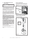
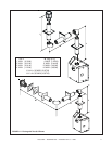
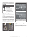
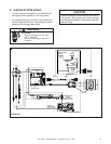
WARNING: ENSURE THAT THE HEATER GASKET
SUPPLIED WITH THE HEATER SEALS BETWEEN
THE FIRST FLUE COMPONENT AND THE OUTER
HEATER WRAP.
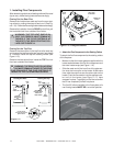
2. Assembling Flue Components
Fire Risk
Exhaust Fumes Risk
Impaired Performance of Appliance
• Overlap pipe slip sections at
least 1-1/2 inches (38.1mm).
• Use pilot holes for screws.
• Screws must not exceed one
inch long.
• Pipe may separate if not properly
joined.
WARNING
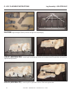
Insert the inner flue of section A into the flared inner flue
of section B.
Start the outer flue of section A over the outer flue of
section B (see Figure 1.18). Note: The end of the pipe
sections with the lances/tabs on it will face towards the
appliance.
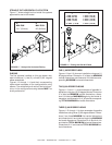
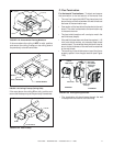
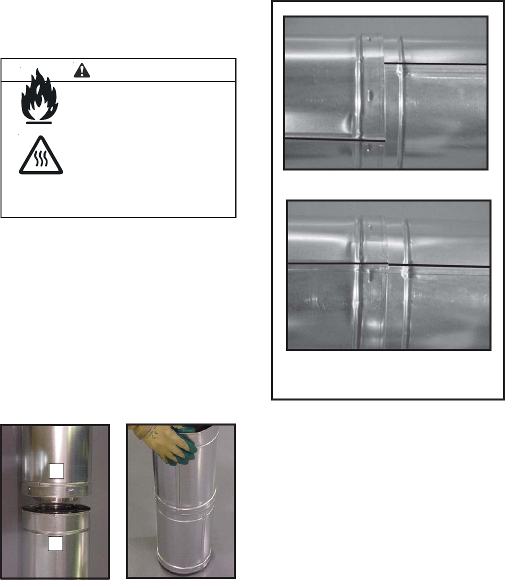
Once both inner and outer flues are started, press sec-
tion A onto section B firmly until all lances have snapped
into place. Check to make sure they have snapped to-
gether (see Figure 1.19) and the seams are not aligned
(see Figure 1.20). Tug slightly on section A to confirm it
has completely locked into place.
Figure 1.18 Figure 1.19
Figure 1.20 Seams
Note: Make sure that the seams are not aligned to
prevent unintentional disconnection.
A
B
CORRECT
INCORRECT
NOTE: Make sure that seams are NOT aligned to
prevent unintentional disconnection.
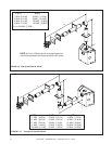
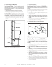
For elbows that are changing the flue direction, two
screws minimum should be put in the outer flue at the
joint to prevent the elbow from rotating.