


Heat & Glo • Cyclone-BN, Cyclone-BC • 2073-900 Rev. N • 10/08 31
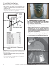
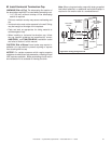
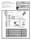
C. Hot Surface Ignition Wiring
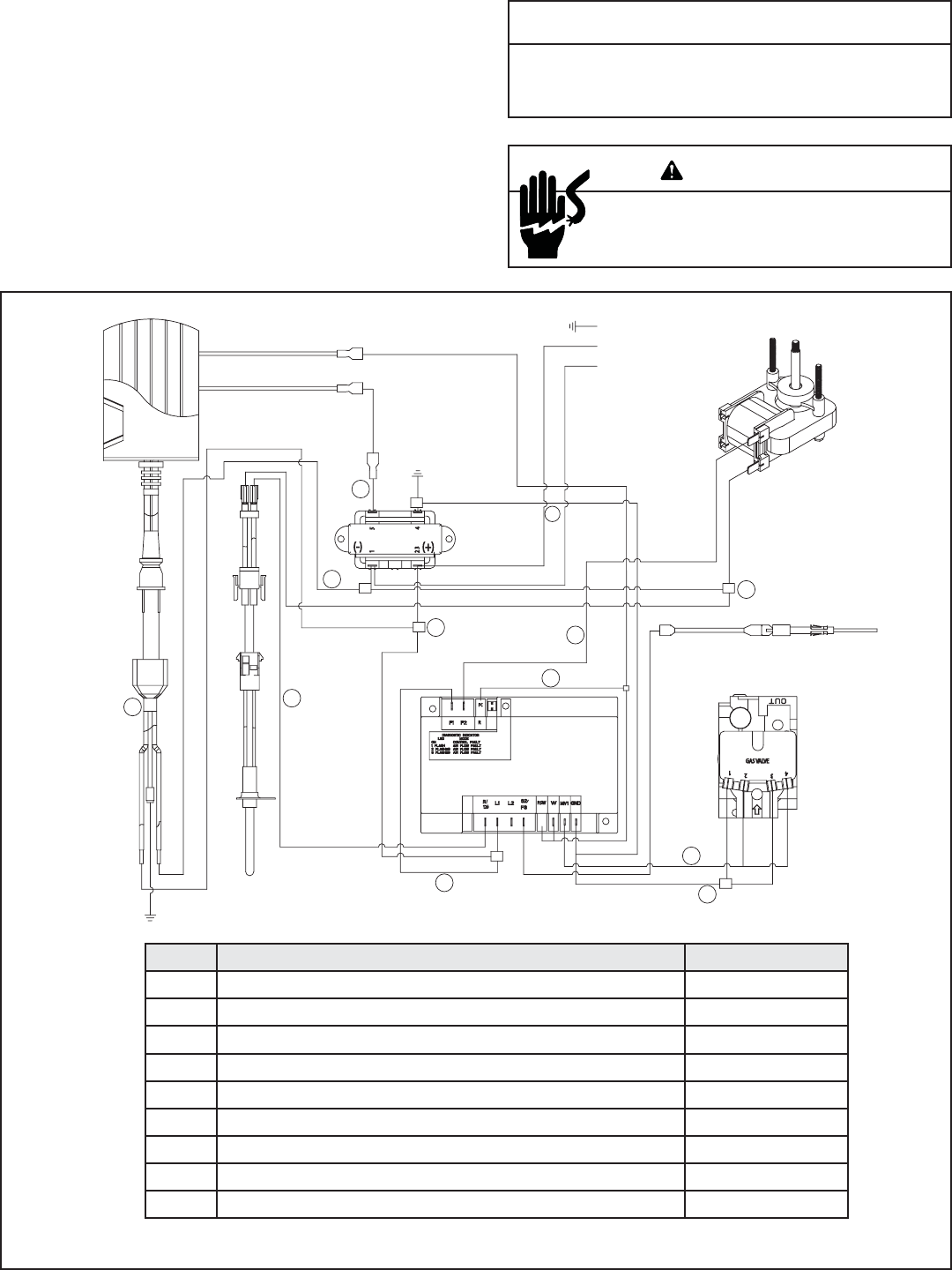
This appliance requires a 110 VAC supply to the appliance
terminal block for operation. A wiring diagram is shown in
Figure 10.3.
This appliance is equipped with a 24V valve.
Optional Accessories Requirements
Wiring for optional accessories should be done now to
avoid reconstruction.
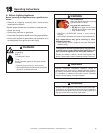
CAUTION
Label all wires prior to disconnection when servicing controls.
Wiring errors can cause improper and dangerous operation.
Verify proper operation after servicing.
Shock hazard.
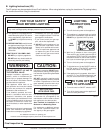
• Replace damaged wire with type 105º C rated wire.
• Wire must have high temperature insulation.
WARNING
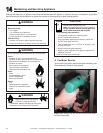
Figure 10.3 Wiring diagram
ITEM PART DESCRIPTION COLOR(S)
1 (M)L1 - (M)F1 - (T) 23 - -120V Black
2 (FT) BTM-IGN-(T)1- +120V Black/White
3 (V)1 & (V)3 - GND & (T)4 Blue/Green
4 (V)2 & (V)4 - (M)MV1 Red
5 (M) F2 - (FT) TOP White
6 (M)S1-IGN White
7 FEMALE RECEPTACLE PLUG Black/White/Green
8 REMOTE WITH PIGTAIL - (M)W OPTIONAL Red
9 (M)R - (M)W - (M)P.SW - REM/WS Red
1
GROUND
(L1) 120-BLACK
(N) NEUTRAL-WHITE
FAN MOTOR
SENSOR
24 VOLT TRANS
CONTROL MODULE
HOT SURFACE IGNITOR
(HSI)
REMOTE
6
2
7
8
3
5
2
9
4
3
1