


Heat & Glo • Cyclone-BN, Cyclone-BC • 2073-900 Rev. N • 10/0830
10
10
Electrical Information
A. Recommendation for Wire
This appliance requires 110-120 VAC be wired directly to
the transformer. See Figure 10.1.
B. Connecting to the Appliance
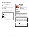
WARNING
• This appliance comes factory wired with a remote control
for operation. The remote can be removed and the
appliance can be wired to run off of a standard wall switch.
Refer to the wiring diagram for more information.
• Keep wire lengths short as possible by removing any
excess wire length.
• Low voltage and 110 VAC voltage cannot be shared
within the same wall box.
Wire 110V to terminal block.
Do NOT wire 110V to valve.
Do NOT wire 110V to wall switch.
• Incorrect wiring will damage this valve.
• Incorrect wiring will override HSI safety lockout
and may cause explosion.
1. Ensure that the electrical service being installed to
the appliance is turned “OFF” by verifying with a volt
meter.
2. Bring the electrical service wire through the wire re-
straint located on the right side of the appliance. Leave
about 10 inches of electric service wire inside the ap-
pliance for the Black (L1) and White (N) wires, leave
16 inches of slack for the service ground wire to reach
its grounding screw located beneath the remote.
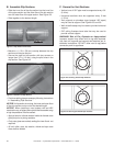
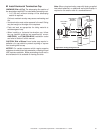
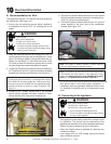
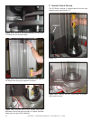
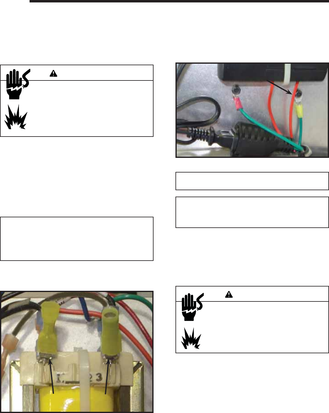
3. Locate the (2) female insulated connectors installed on
the Transformer and the (1) ground connector screwed
beneath the remote control receiver. See Figure 10.1.
Note: The factory installed yellow female insulated connectors
(2) and yellow ground connector (1) are designed for use with
10/12 AWG wire. If another gauge wire is being used, these
connectors should be replaced with the appropriate gauge
insulated connectors to ensure a proper connection. See
Figure 10.1.
Note: The system is polarity sensitive. Polarity must be
correct for this fi replace to operate correctly.
Connectors are factory installed.
Connectors are factory installed.
These are approved for 10/12 AWG wire.
These are approved for 10/12 AWG wire.
Figure 10.1
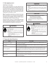
Shock hazard.
Wire 110V to transformer.
Do NOT wire 110V to valve.
Do NOT wire 110V to wall switch.
• Incorrect wiring will damage millivolt valves.
• Incorrect wiring will override HSI safety lockout
and may cause explosion.
WARNING
23
23
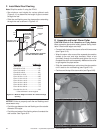
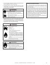
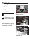
1
1
Shown after service
Shown after service
ground wire was attached
ground wire was attached
Figure 10.2
4. Connect the L1 (Black) service wire to the supplied
yellow female insulated connector located on trans-
former terminal (23) using a wire crimping tool.
5. Connect the neutral (White) service wire to the yellow
female insulated connector located on transformer ter-
minal (1) using a wire crimping tool.
6. Connect the ground (Green) wire to the 1/4 in. ground
screw located on the front right of the transformer
bracket. See Figure 10.2.
Note: This appliance must be electrically wired and grounded
in accordance with local codes or, in the absence of local
codes, with National Electric Code ANSI/NFPA 70-latest
edition or the Canadian Electric Code, CSA C221.1.
• A 110-120 VAC circuit for this product must be protected
with ground-fault circuit-interrupter protection, in
compliance with the applicable electrical codes, when
it is installed in locations such as in bathrooms or near
sinks.