


Heat & Glo • Cyclone-BN, Cyclone-BC • 2073-900 Rev. N • 10/0820
7
7
Appliance Preparation
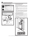
A. Securing and Leveling the Appliance
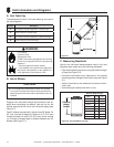
Fire Risk.
• ALWAYS maintain specifi ed
clearances around the appliance.
• Do NOT notch into the framing around the appliance spacers.
Failure to keep insulation, framing or other material away from
the appliance may cause fi re.
Fire Risk.
• Prevent contact with sagging, loose insulation.
• Do NOT install against combustible materials
such as exposed insulation, plastic and insulation
backer.
WARNING
WARNING
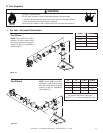
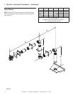
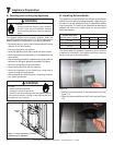
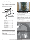
The diagram shows how to properly position, level, and
secure the appliance (see Figure 7.1). Nailing tabs are pro-
vided to secure the appliance to the framing members.
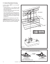
• Horizontal venting - refer to Vent Clearances and Framing
(Section 6) for hole location.
• Place the appliance into position.
• Level the appliance from side to side and front to back.
• Shim the appliance as necessary. It is acceptable to use
wood shims.
• Ensure that top and bottom of appliance are square with the
back prior to nailing the appliance completely into place.
• Bend up nailing tabs on top and bottom.
• Keep nailing tabs fl ush with the framing.
• Secure the appliance to the framing by using nails or
screws through the nailing tabs.
• After appliance is nailed into place, remove top and bot-
tom squaring brackets.
Figure 7.1 Proper Positioning, Leveling
and Securing of a Appliance
NAILING
TABS
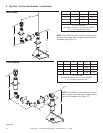
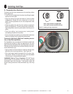
B. Installing Exhaust Baffl e
This appliance is supplied with three different sized exhaust
baffl es, found in the manual bag assembly. Depending on
the vent run for the installation one of the exhaust baffl es
may be required. To install one of the baffl es for best fl ame
appearance refer to the table below for exhaust baffl e
recommendations.
The above table is a guideline. Depending on the amount
of elbows or horizontal in your system you may or may not
have to use any of the three baffl es.
Vertical Vent Runs
greater than or equal to
Exhaust Baffl es
3-1/4 in. 2-3/4 in. 2-1/4 in.
6 Feet X
15 Feet X
20 Feet X
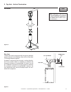
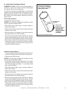
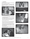
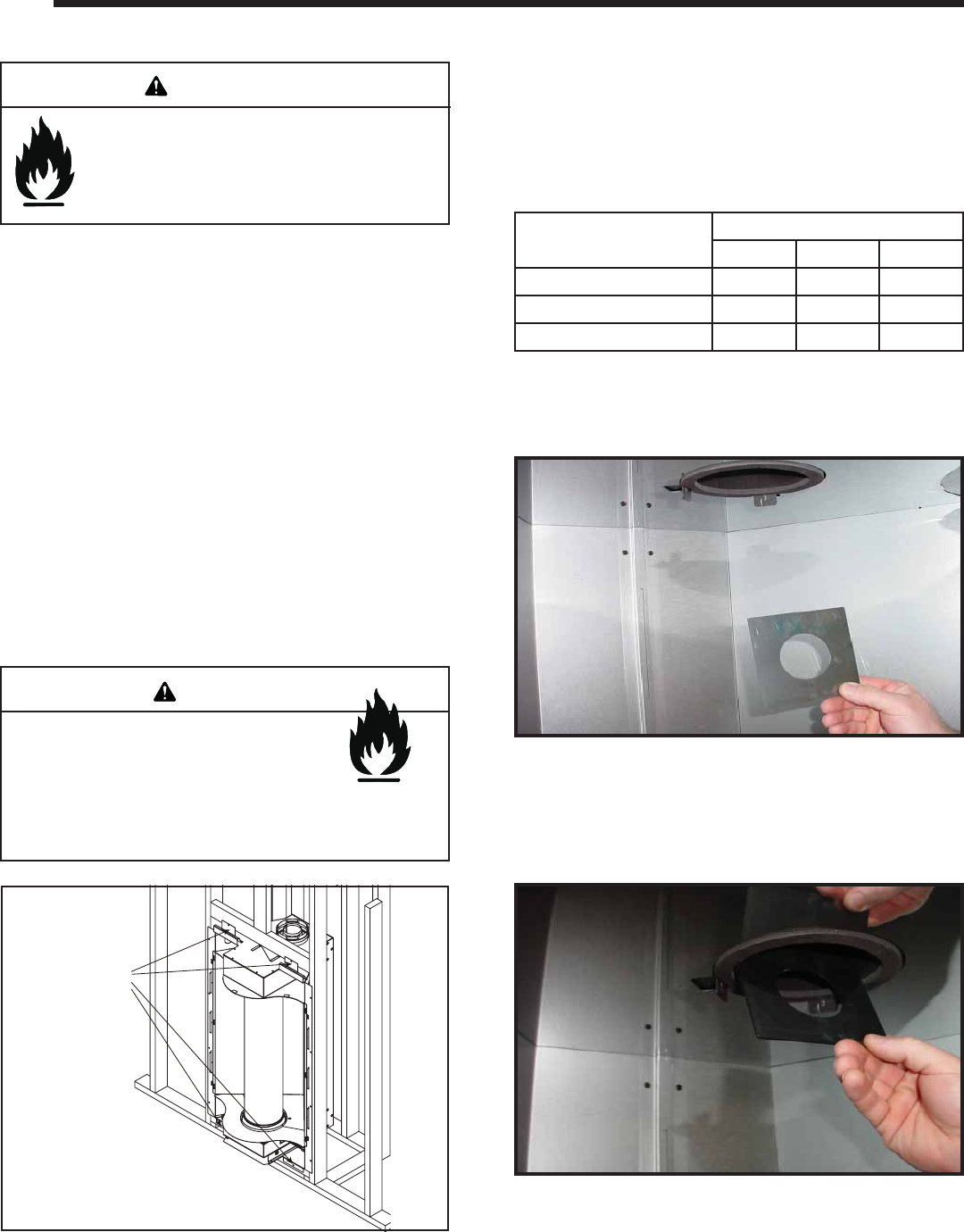
• Position the exhaust baffl e in the top exhaust hole (see
Figure 7.2).
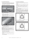
• Center the exhaust baffl e over the 5 inch hole (see Figure
7.3).
Figure 7.3
Figure 7.2