


Heat & Glo • Cyclone-BN, Cyclone-BC • 2073-900 Rev. N • 10/08 13
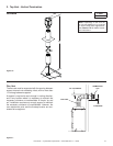
V
T
H
T
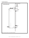
Figure 5.3
Figure 5.4
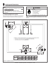
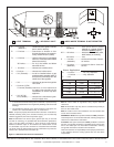
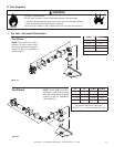
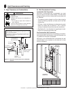
D. Vent Diagrams
1. Top Vent - Horizontal Termination
One Elbow
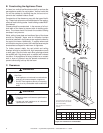
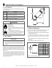
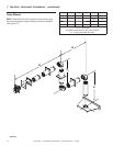
Two Elbows
H
2
H
1
V
T
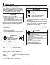
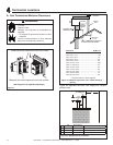
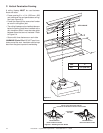
Fire Risk. Explosion Risk.
Do NOT pack insulation or other combustibles between ceiling fi restops.
• ALWAYS maintain specifi ed clearances around venting and fi restop systems.
• Install wall shield and ceiling fi restops as specifi ed.
Failure to keep insulation or other material away from vent pipe may cause fi re.
WARNING
V
T
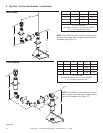
Min. H
T
Max.
1.5 ft. 2 ft.
2.5 ft. 5 ft.
3.5 ft. 8 ft.
4.5 ft. 11 ft.
V
T
+ H
T
= 40 ft. Max
H
1
H
2
V
T
Min. H
T
Max.
**
1.5 ft. 2 ft.
**
2.5 ft. 5 ft.
**
3.5 ft. 8 ft.
**
4.5 ft. 11 ft.
V
T
+ H
T
= 40 ft. Max.
*No specifi c restrictions on this value
EXCEPT V
T
+ HT cannot exceed 40 ft. Max.
NOTE: There MUST be a 25%
reduction in total H when using
fl ex vent except when using the
simple up and out installation
(see Figure 5.7).
NOTE: There MUST be a 25%
reduction in total H when using
fl ex vent except when using the
simple up and out installation
(see Figure 5.7).