


Page 94
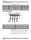
Analog Inputs
8990cm.fm
Section 6
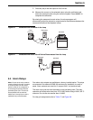
There are a total of three analog input channels available on the sampler.
These inputs accept 4–20 mA dc or -4.0 to +4.0 V dc analog signals. They
can be logged and graphed and can also be used to trigger alarms, cause
setpoint samples, and control 4–20 mA outputs.
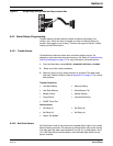
6.5.2 Analog Inputs Programming
Analog input channels can accept a signal from an external device. This
signal may range from -4.0 V dc (min) to +4.0 V dc (max) or from 4 to 20 mA
dc depending on the input selected. In some cases, input signals from certain
devices may also fall somewhere within those ranges. For that reason, each
analog input channel must be mapped to the minimum and maximum signal
limits of the external device.
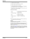
To map an external device to an analog input channel:
1. From the Main Menu, select
OPTIONS>ADVANCED OPTIONS>DATALOG.
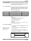
2. Highlight Select Inputs using the UP and DOWN keys and press SELECT.
Note: If logging is enabled on any
channel, then that channel will have
an arrow in front of the channel
name to signify the channel
is logged.
3. Highlight the analog channel to log using the UP and DOWN keys, then
press
SELECT.
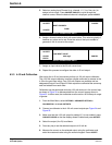
4. Press
CHANGE CHOICE to cycle between Logged and Not Logged, then
press
ACCEPT.
5. Enter a Logging Interval using the numeric keypad. Press
ACCEPT to
continue.
6. Select Unit of measurement (ppm, ppb, afd, cfs, cfm, cfd, cms, cmm, cmh,
cmd, gps, gpm, gph, lps, lpm, lph, or mgd).
7. Enter Low Point.
8. Enter High Point.
9. Select another channel to configure, or press
RETURN to back up one
step. Press
MAIN MENU to return to the Main Menu display.