


Section 7
Page 101
8990mnt.fm Circuit Board Identification
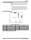
7.7 Circuit Board Identification
There are two main circuit boards in the sampler; the Utility Board and the
CPU board. The CPU board is attached to the bottom panel and the Utility
board is located inside the control housing behind the motor/gearbox
assembly.
Note: Removal and handling of the circuit boards used in the sampler requires
knowledge of ESD (Electro-Static Discharge) precautions and the CMOS
(Complementary Metal-Oxide Semiconductor) circuit components used in the
sampler. Static electricity has the potential to damage the CMOS components of
the sampler when the boards are unplugged and removed from the case.
Precautions must be taken to assure static-free personnel and work area prior to
handling the circuit boards.
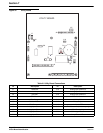
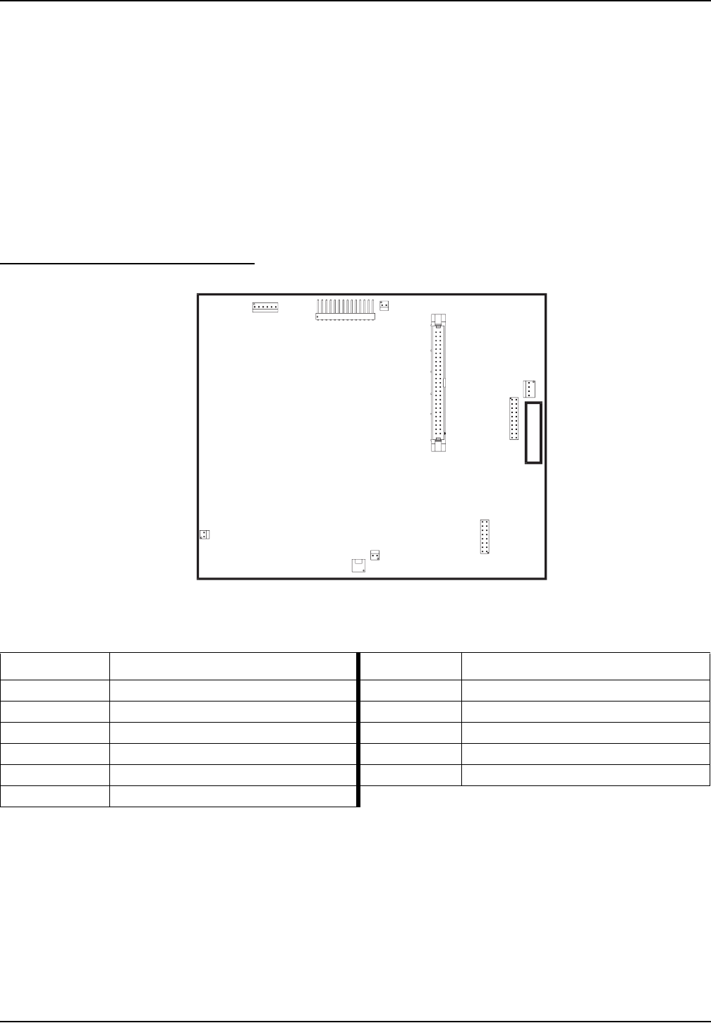
Figure 31 CPU Board
Table 20 CPU Board Connectors
ID Description ID Description
J1 Liquid Crystal Display J7 RS485 Submerged Pressure Transducer
J2 Mechanical Totalizer J8 Modem Option Module
J3 not used J9 Liquid Crystal Display (LED back-light)
J4 Base Board J10 Keypad
J5 Memory Backup Battery Pack J11 not used
J6 RS232 Serial Port
CPU BOARD
J6
J10
J9
J11
J2
J5
J8
J4
J1
J7
F1