


Do not attempt to repair your water heater. Call a qualified
Oil-Burner Technician for service. Turn “OFF” the electric
power whenever the water supply is shut off. Before calling
for service, check that:
1. The heater is properly filled.
2. The electrical supply has not been interrupted.
Professional Maintenance
Except for external appearance and area tidiness, the fol-
lowing steps should be performed only by a qualified Oil-
Burner Technician.
1. Lift out the flue baffle to clean the flue. (On rear and
combination flue heaters, the top cover, insulation and
flue top cover must be removed.)
2. Insert a flue brush down the flue passage way(s) to
remove soot and dirt. Soot or carbon that falls into the
combustion chamber will burn up within a very short
time.
3. In normal use, there should be no large accumulation of
soot in the combustion chamber. If there is, remove the
burner and carefully brush or vacuum the combustion
chamber.
Flue Pipes
Once a year, inspect the flue pipe leading from the heater to
the chimney. If corrosion is evident, or discolouration at the
joints can be seen, replace the flue pipes. This should be
done by a qualified Oil-Burner Technician. Flue pipes must
be replaced by the same size flue pipe as the flue collar
(breech connection) at the heater.
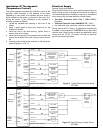
Combustion Tests
Burner adjustments:
Final burner adjustments must be made using combustion
test equipment to assure proper operation. Do not fire
heater without water or sections will overheat.
1. Refer to burner manual for start-up.
2. Allow heater to heat to design condition.
3. Using combustion test equipment, adjust burner for:
a. CO
2
between 11% and 12% and a trace of smoke
between No. 0 smoke and No. 1 smoke.
b. over-fire draft -0.01 to -0.02 in. w.c. (-0.0025 to -
0.005kPa) draft in combustion chamber (+0.25 in.
w.c. (+0.062kPa) for JWF307V).
NOTE: For JWF307V also see additional “Installation
Instructions for Through-the-wall Venting Components" that
is supplied with the JWF307V.
Routine Preventative Maintenance (by
owner/operator)
As a precaution against fire, and to maintain an adequate
flow of combustion air to the heater:
• Keep the appliance area clear and free from combustible
material, gasoline and other flammable vapors and liq-
uids.
• Keep the air ventilation openings unobstructed. If dust
and lint is seen accumulating around the openings,
remove it.
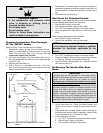
• Do not pile cartons, papers, or combustible materials on
top, or near the heater (see Figure 1).
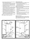
Draining and Flushing
It is recommended that the tank be drained and flushed
every 6 months to remove sediment that may build up dur-
ing operation. The water heater should be drained if being
shut down during freezing temperatures. To drain the tank,
perform the following steps:
1. Turn off the electrical supply to the water heater.
2. Close the cold water inlet valve.
3. Open a nearby hot water faucet.
4. Connect a hose to the drain valve and terminate it to an
adequate drain.
Note: The drain hose should be rated for at least 93°C
(200°F). If the drain hose does not have this rating, open the
cold water inlet valve and a nearby hot faucet until the water
is no longer hot.
5. Open the water heater drain valve and allow all the
water to drain from the tank. Flush the tank with water
as needed to remove sediment.
6. Close the drain valve, refill the tank, and restart the
heater as directed under “Water Heater Operation”.
If the water heater is going to be shut down for an extended
period, the drain valve should be left open.
Important: Condensation may occur when refilling the tank
and should not be confused with a tank leak.
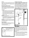
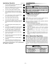
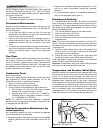
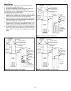
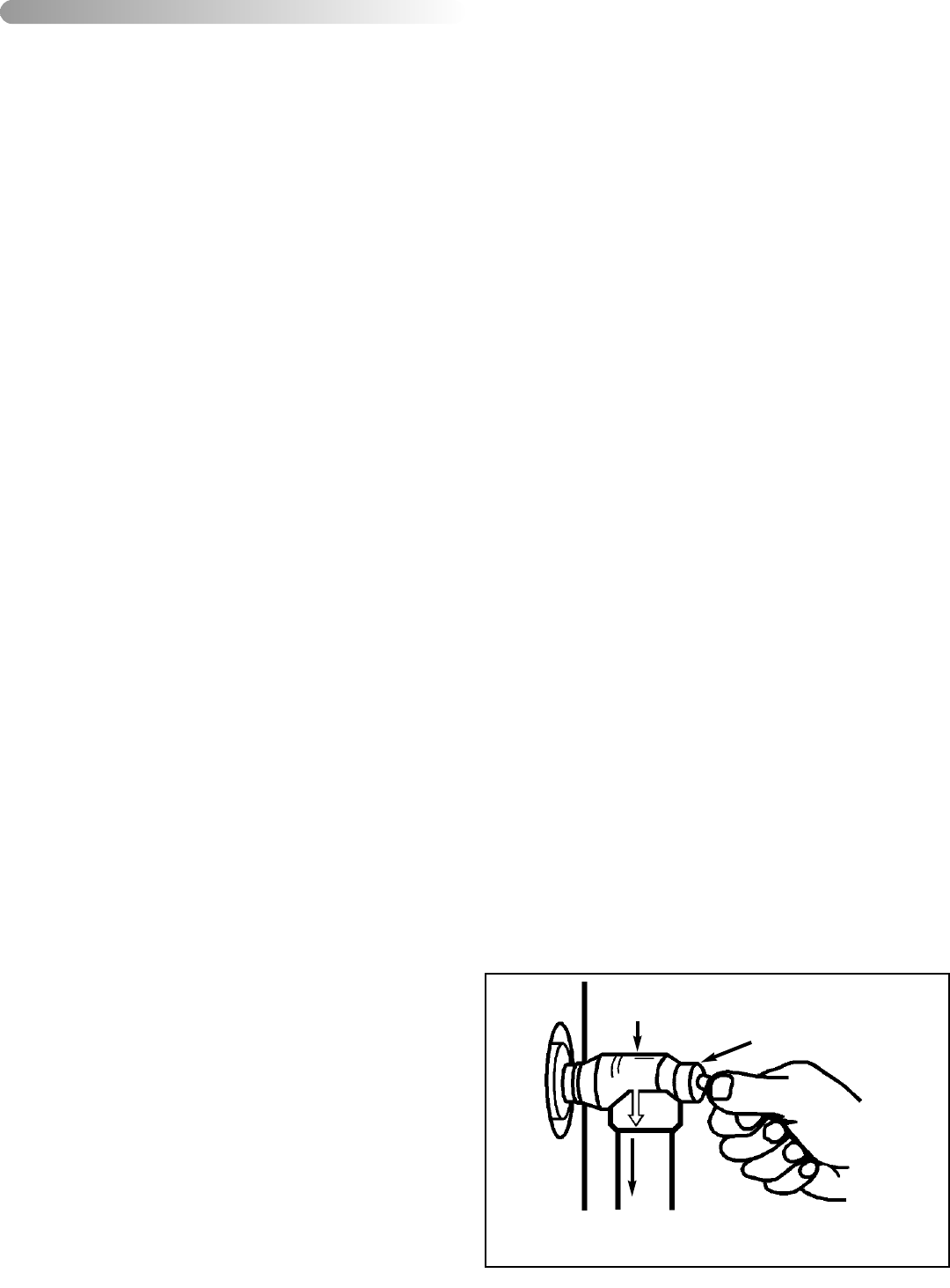
Temperature and Pressure Relief Valve
Manually operate the temperature and pressure relief valve
at least once a year to make sure it is working properly (see
Figure 12). To prevent water damage, the valve must be
properly connected to a discharge line that terminates at an
adequate drain. Standing clear of the outlet (discharged
water may be hot), slowly lift and release the lever handle on
the temperature and pressure relief valve to allow the valve
to operate freely and return to its closed position. If the valve
fails to completely reset and continues to release water,
immediately shut off the power to the heater and the cold
water inlet valve and call a qualified service technician.
V) MAINTENANCE
– 18 –
Temperature and Pressure
Relief Valve
Manual Relief Valve
Discharge line to drain
Figure 12 T&P Valve Test