


– 11 –
Chimney
Be sure that the chimney is sufficiently high and large
enough to meet the specifications of the burner unit
installed. Check that there is sufficient draft for the proper
burning of oil. At least -0.015 in. w.c. (-0.004kPa) of over-fire
draft is recommended.
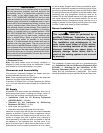
Blocked Vent Safety Switch
Oil-fired water heaters must be fitted with the blocked vent
safety switch supplied with your heater. The installation pro-
cedure is given below. For further details and information
refer to the instruction sheet supplied with the switch. (Not
required for JWF307V.)
Installation
1. Pierce a 16mm (5/8 in.) dia. hole into the flue pipe
305mm to 457mm (12 to 18 in.) from the breech con-
nection of the water heater. Remove one of the securing
nuts from the pipe of the safety switch. Tighten the other
securing nut onto the pipe as far as possible.
2. Insert the threaded pipe end into the pierced hole, then
install the securing nut, which was removed in step 1,
and tighten securely.
CAUTION:: Turn "OFF" the electrical supply to the water
heater when wiring safety switch.
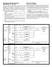
3. Wire the safety switch in series with L1 of the electrical
supply (see Figures 9, 10 & 11). Install and route wiring
in an accordance with “Canadian Electrical Code Part
1 (C22.1)” and any applicable local codes.
CAUTION: If for any reason the system has shut down
during operation, the cause of the system failure should be
investigated and corrected before resetting the safety switch
and re-starting the system.
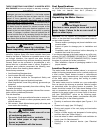
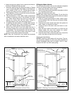
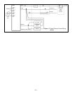
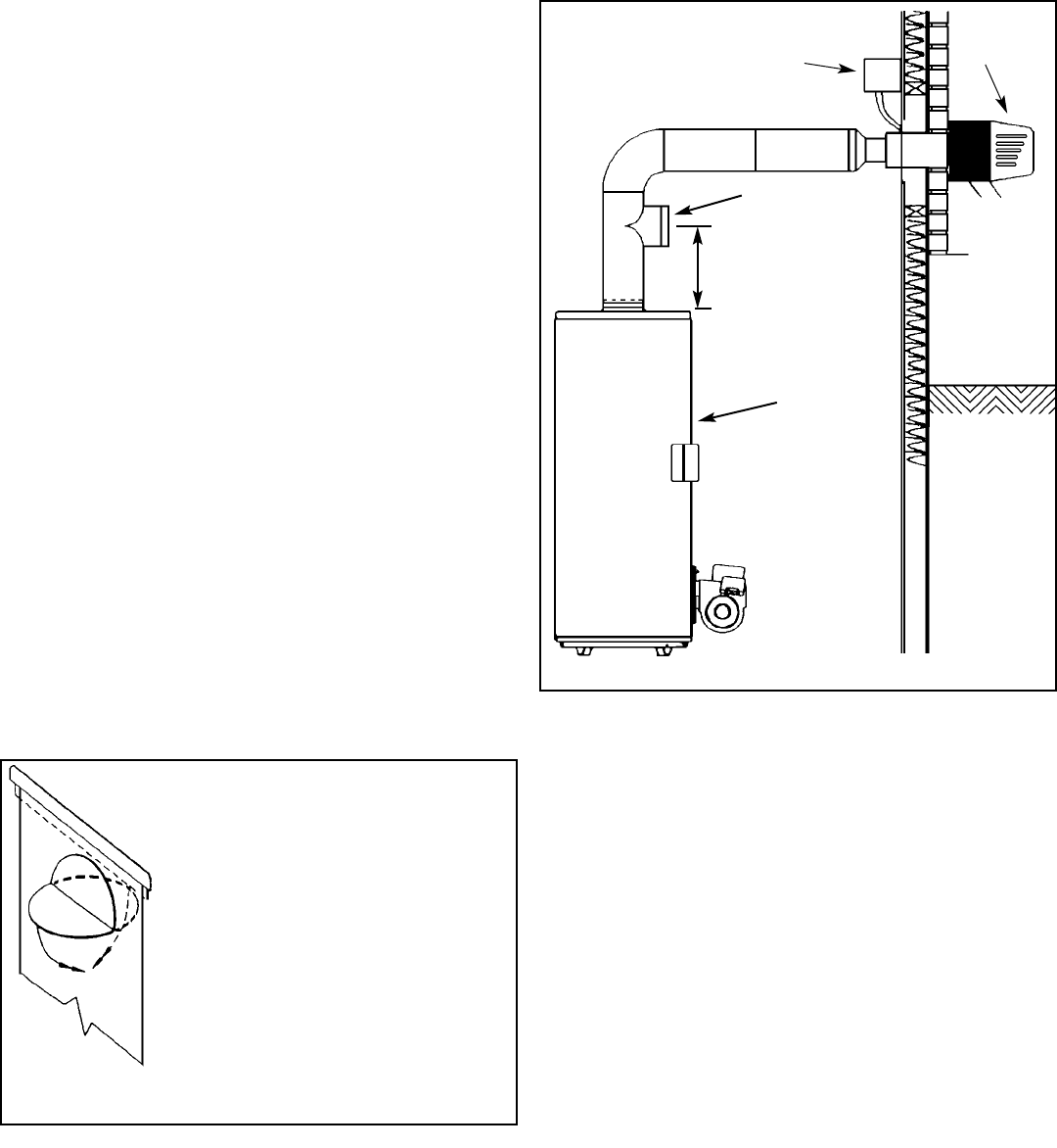
Power Venting
Models JWF307, JWF507 and JWF657 may be power vent-
ed with a Field SWGII 4HD Power Venter. The following
control kits may be used with the SWGII 4HD:
CK 61 Electronic Post Purge.
CK 62 Thermally Activated Post Purge.
Installation of Power Venter
The “Installation Code for Oil-Burning Equipment (CSA
B139-04)” or “Standard for the Installation of Oil-
Burning Equipment (NFPA 31)”, local codes and the man-
ufactures instructions should be adhered to in all installa-
tions of the water heaters and power venters. A draft regu-
lator must be used in conjunction with the installation of the
power venter (see “Draft Regulator”). Consult the applicable
codes to calculate the equivalent length of pipe for each fit-
ting in the vent system. Add this (equivalent) length to the
length of the straight runs of pipe to determine the total
equivalent vent pipe length.
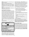
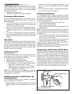
Water Supply
Piping Installation
Piping, fittings, and valves should be installed according to
the applicable installation drawing (Figures 7 & 8). A pres-
sure-reducing valve and/or an expansion tank may be
required for installations where the water pressure is high.
The pressure-reducing valve should be located on the sup-
ply to the entire house in order to maintain equal hot and
cold water pressure.
Important:
• Do not apply heat to the water fittings on the heater as
they may contain nonmetallic parts. If solder connections
are used, solder the pipe to an adaptor before attaching
the adaptor to the hot and cold water fittings.
• Some models may contain energy saving heat traps to
prevent the circulation of hot water within the pipes. Do
not remove the inserts within the heat traps.
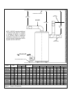
CK SERIES
CONTROL KIT
DRAFT
REGULATOR
OIL FIRED
WATER
HEATER
SWG II 4HD
POWER
VENTER
Figure 6 Power Venting
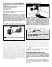
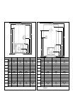
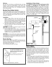
BEND DOWN
WHEN MODEL JWF307 IS TO BE FIRED AT
THE MAXIMUM RECOMMENDED RATE OF
0.75 GPH, THE FLUE BAFFLE MUST BE
ALTERED AS IN THE DIAGRAM. BOTH HALF
DISCS MUST BE BENT FLAT AGAINST THE
BODY OF THE BAFFLE.
THIS IS REQUIRED TO ALLOW FLUE GAS
PASSAGE AT THE HIGHER FIRING RATE.
Figure 5 Baffle Modification (JWF307)
SEE MANUFACTURER’S
INSTRUCTIONS