


– 10 –
appliances in the enclosure, freely communicating with inte-
rior areas that have in turn adequate infiltration from the out-
side. It shall also have a combustion air supply opening so
that the total air received through the opening will be at least
as much as would be admitted by openings having a total
free area of 4.5 cm
2
/kWh (1 in
2
/5000 Btu/h) of the total input
rating of all oil-fired appliances in the enclosure.
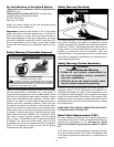
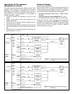
Indoor Combustion & Ventilation Air (Confined
space)
A heater installed in a confined space and that obtains all of
its air for combustion and ventilation from within the condi-
tioned space of the building shall be provided with two per-
manent openings, one near the top of the enclosure and
another near the bottom. Each opening shall have a free
area of not less than 19.5 cm
2
/kWh (1 in
2
/1000 Btu/h) of the
total input rating of all appliances in the enclosure, freely
communicating with interior areas that have in turn ade-
quate infiltration from the outside.
Air Duct Sizing
The air duct requirements shall be met by one of the follow-
ing methods:
1. vertical duct(s) with a free area of not less than 5.5
cm
2
/kWh (1 in
2
/4000 Btu/h) of the total input rating of all
appliances in the enclosure;
2. horizontal duct(s), with an equivalent length of less than
15 m (50 ft), having a free area of not less than 11
cm
2
/kWh (1 in
2
/2000 Btu/h) of the total input of all appli-
ances in the enclosure; and
3. air openings that communicate directly with the out-
doors, having a free area of not less than 5.5 cm
2
/kWh
(1 in
2
/4000 Btu/h) of the total input rating of all appli-
ances in the enclosure.
NOTE: Duct runs that are primarily horizontal and that have
an equivalent length greater than 15 m (50 ft) should be
sized accordingly larger to provide the same air flow as
would be provided by the requirements of method (3) above.
In U.S.A.:
Refer to “Standard for the Installation of Oil-Burning
Equipment (NFPA 31)”
Vent and Exhaust Connections
General chimney requirements
For a burner designed for natural draft connect the vent to a
vertical chimney. Insufficient draft can cause flue gas leak-
age and carbon monoxide emissions, which can lead to
severe bodily injury or death. Use vent material approved by
local codes for oil-fired burners. In the absence of such
codes, refer to:
• “Installation Code for Oil-Burning Equipment (CSA
B139-04)” (Canadian installations).
• “Standard for the Installation of Oil-Burning
Equipment (NFPA 31)” (USA).
• “Standard for Chimneys, Fireplaces, Vents, and Solid
Fuel-Burning Appliances (NFPA 211)” (USA).
NFPA 211 requires the chimney to be lined before connect-
ing the oil-fired water heater. Inspect existing chimney
before installing the water heater. Failure to do any of the
following can result in serious property damage, severe
bodily injury or death:
• Clean the chimney, including removal of blockage.
• Repair or replace damaged pipe or liner.
• Repair mortar and joints.
To prevent downdrafts, extend the chimney at least 1m (3 ft.)
above the highest point where it passes through the roof
and 600mm (24 in.) higher than any portion of the building
within 3m (10 ft.). Increase chimney cross-sectional area
and height at least 4% per 305m (1,000 ft.) above sea level.
Flue Pipe
NOTE: Type “L” vent material is generally considered to be
not suitable for this application. Flue temperatures may
exceed 300°C (572°F). Use flue piping approved for this
installation.
Long horizontal flue pipes, excessive number of tees and
elbows or other obstructions restrict flue gas flow, and can
result in the possibility of condensation, flue gas leakage
and carbon monoxide emissions. These conditions can lead
to serious property damage, severe bodily injury or death.
The flue pipe should be the same size as the breech con-
nection on the appliance. The sizes generally are 150mm (6
in.) for burners rated less than 1.00 GPH and 178mm (7 in.)
for burners rated 1.00 to 1.50 GPH. The flue pipe should be
as short as possible and installed so that it has a continuous
rise of 20mm/m (1/4 in./ft.) of horizontal length from the
breech connection on the appliance to the chimney. Elbows
should be minimized and the sections of pipe and fittings
should be joined with sheet metal screws and straps.
Routing should be made in such a way as to avoid sharp
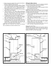
turns or unduly long runs. It is recommended that the heater
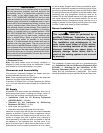
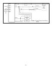
be piped to its own individual flue. Where there is only one
flue for both furnace and water heater, various methods are
practiced in which the water heater flue enters the chimney
above the main smoke pipe. Also, a “Y” fitting is frequently
used to combine the heater and furnace flues, prior to enter-
ing the chimney connection (see Figure 4, check with local
authorities having jurisdiction). Obtain a gas-tight seal to
prevent possible flue gas leakage and carbon monoxide
emissions, which can lead to severe bodily injury or death.
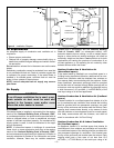
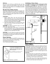
Draft Regulator
This device is used on conventional chimney venting only. It
automatically maintains a constant negative pressure in the
chimney to obtain maximum efficiency. If the chimney does
not develop sufficient draft, the draft control cannot function
properly. The heater must be equipped with an approved
draft regulator of adequate size. Ensure the draft regulator
diameter is at least as large as the flue pipe diameter. Follow
manufacturers recommended instructions for installation. It
must be installed in the flue pipe before it enters the chim-
ney and after the Blocked Vent Safety Switch, if one is used.
Set the draft regulator at -0.03 in. w.c. (-0.0075kPa), as
measured in the flue (between the heater and the draft reg-
ulator). Recommended over-fire draft is -0.02 in. w.c. (-
0.005kPa).