


– 12 –
• Always use a proper grade of joint compound and be cer-
tain that all fittings are drawn up tight.
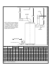
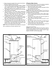
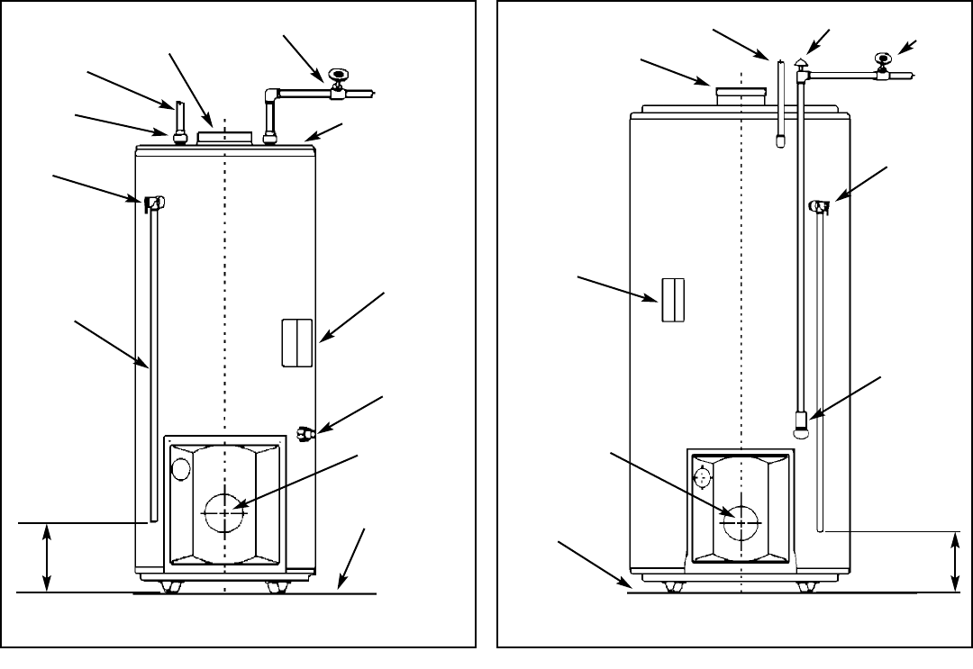
1. Install the water piping and fittings as shown in Figures
7 or 8. Connect the cold water supply to the fitting (3/4”
NPT) marked “COLD” (or “C”). Connect the hot water
supply to the fitting (3/4” NPT) marked “HOT” (or “H”).
2. The installation of unions in both the hot and cold water
supply lines is recommended.
3. The manufacturer of this water heater recommends
installing a tempering valve in the domestic hot water
line. These valves reduce the point-of-use water tem-
perature by mixing cold and hot water. Contact a
licensed plumber or the local plumbing authority.
4. If installing the water heater in a closed water system,
install an expansion tank in the cold water line as spec-
ified under “Closed System/Thermal Expansion”.
5. Install a shut-off valve in the cold water inlet line. It
should be located close to the water heater and be eas-
ily accessible. The owner/operator must be shown the
location of this valve and be given instructions on how
to use it to shut off the water to the heater.
NOTE: Rear and Combination flue heaters are equipped
with a combination cold water inlet/drain valve.
Filling the Water Heater
Do not insert the power cord into the electrical receptacle
until all the following steps have been completed.
1. Make sure the drain valve is closed.
2. Open all hot water faucets served by the system to allow
air to escape from the tank.
3. Open the cold water inlet valve.
NOTE: When filling, avoid water leakage. Do not allow the
insulation of the water heater to get wet as water can reduce
the effectiveness of the insulation.
4. When an uninterrupted stream of water, without appar-
ent air bubbles, flows from the open hot water faucets,
the tank is full.
5. Close the hot water faucets and check the system for
leaks. Repair as required and retest.
6. Connect a hose to the drain valve and route to a suit-
able drain.
7. Open the drain valve and let water run to flush out any
foreign matter that may have entered the system.
Continue flushing until clean water flows.
8. Close the drain valve, disconnect the hose, ensure the
drain valve does not drip and re-fill the tank.
Please note the following:
DO NOT install this water heater with iron piping. The sys-
tem should be installed only with piping that is suitable for
potable (drinkable) water such as copper, CPVC or poly-
butylene. DO NOT use PVC water piping.
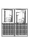
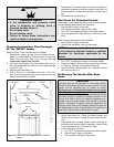
COLD WATER
SHUT-OFF
AQUASTAT
TEMPERATURE
CONTROL
T&P VALVE
COLD INLETAND
DRAIN VALVE
COMBINATION
HOT WATER
OUTLET
Figure 8 Plumbing Connections (Center/Rear Flue)
150 TO
305mm
6 TO 12”
FLUE COLLAR
CAPPED FOR REAR
FLUE USE (OPTIONAL)
VACUUM BREAKER
CENTER OF
BLAST TUBE
NON-COMBUSTIBLE
FLOOR
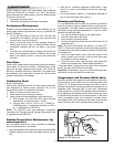
COLD WATER
SHUT-OFF
AQUASTAT
TEMPERATURE
CONTROL
T&P VALVE
DRIP TUBE
DRAIN
VALVE
HOT WATER
OUTLET
Figure 7 Plumbing Connections (Center Flue)
150 TO
305mm
6 TO 12”
CENTER OF
BLAST TUBE
NON-COMBUSTIBLE
FLOOR
TOP
NIPPLE
BREECH
CONNECTION