


– 14 –
Installation Of The Aquastat
(Temperature Control)
This heater operates automatically under the control of the
aquastat, which responds to the demand of hot water.
Depending on the model, the aquastat well and wiring is
either installed on the heater, or included in the carton con-
taining the burner. If the installation of the aquastat is
required, proceed as follows:
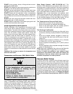
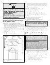
1. Locate the aquastat well opening in the front of the
heater.
2. Apply a good grade of pipe joint compound to the
threads on the well.
3. Install the well in the tank opening, tighten firmly to
ensure there are no leaks.
4. Insert the sensing bulb of the aquastat into the well and
secure the aquastat to the well using the screw provid-
ed.
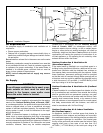
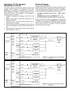
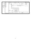
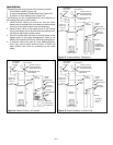
5. Wire the control to the burner as shown in the wiring dia-
grams (Figures 9, 10 & 11).
Electrical Supply
General wiring requirements:
Electric shock hazard. Can cause severe personal injury or
death if power source, including service switch on heater, is
not disconnected before installing or servicing. Installations
must comply with the latest editions of these codes:
• “Canadian Electrical Code Part 1 (CSA C22.1)”
(Canada).
• “National Electrical Code, ANSI/NFPA 70”, (USA).
• Any additional local, provincial, national or state codes.
Wiring must be N.E.C. Class 1. If original wire supplied with
the heater is to be replaced, TYPE 105°C wire or equivalent
must be used. Supply wiring to heater and additional control
wiring must be 14 GA. or heavier. Provide an electrical
ground as required by codes.
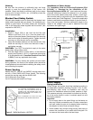
LINE VOLTAGE
THERMOSTAT OR
AQUASTAT®
CONTROL
OIL VALVE
BURNER
MOTOR
IGNITOR
CAD
CELL
LIMIT
TO
REMOTE
ALARM
CIRCUIT
JUMPER
ENVIRACOM™
TERMINAL
L1
LIMIT
L2
VALVE
CAD
CELL
ALARM
T
T3
2
1
VIOLET
WHITE
BLUE
ORANGE
RED
BLACK
YELLOW
YELLOW
BURNER
MOTOR
IGNITOR
R7184
BURNER JUNCTION BOX
Figure 9 Typical Primary Control Wiring
(R7184P).
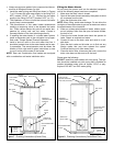
BLOCKED
VENT
SAFETY
SWITCH
L1 HOT
L2 NEUTRAL
LINE VOLTAGE
THERMOSTAT OR
AQUASTAT®
CONTROL
OIL VALVE
BURNER
MOTOR
IGNITOR
CAD
CELL
LIMIT
TO
REMOTE
ALARM
CIRCUIT
JUMPER
ENVIRACOM™
TERMINAL
L1
L2
VALVE
CAD
CELL
ALARM
T
T3
2
1
VIOLET
WHITE
BLUE
ORANGE
BLACK
YELLOW
YELLOW
BURNER
MOTOR
IGNITOR
R7184
BURNER JUNCTION BOX
Figure 10 Typical Primary Control Wiring
(R7184B).
BLOCKED
VENT
SAFETY
SWITCH
L1 HOT
L2 NEUTRAL