


– 13 –
DO NOT use any pumps, valves, or fittings that are not com-
patible with potable water.
DO NOT use valves that may cause excessive restriction to
water flow. Use full flow ball or gate valves only.
DO NOT use any lead based solder in potable water lines.
Use appropriate tin-antimony or other equivalent material.
DO NOT tamper with the aquastat, burner or temperature
and pressure relief valve. Tampering voids all warranties.
Only qualified service technicians should service these com-
ponents.
DO NOT use with piping that has been treated with chro-
mates, boiler seal, or other chemicals.
DO NOT add any chemicals to the system piping which will
contaminate the potable water supply.
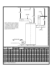
Closed System/Thermal Expansion
Periodic discharge of the temperature and pressure relief
valve may be due to thermal expansion in a closed water
supply system. The water utility supply meter may contain a
check valve, backflow preventer or water pressure-reducing
valve. This will create a closed water system. During the
heating cycle of the water heater, the water expands caus-
ing pressure inside the water heater to increase. This may
cause the temperature and pressure relief valve to dis-
charge small quantities of hot water. To prevent this, it is rec-
ommended that a diaphragm-type expansion tank (suitable
for potable water) be installed on the cold water supply line.
The expansion tank must have a minimum capacity of 5.6
litres (1.5 US gallons) for every 190 litres (50 US gallons) of
stored water and be rated at the working pressure of the
water heater. Contact the local water supplier or plumbing
inspector for information on other methods to control this sit-
uation.
Important: Do not plug or remove the temperature and
pressure relief valve.
Temperature and Pressure (T&P) Relief Valve
For protection against excessive pressures and tempera-
tures, a temperature and pressure relief valve must be
installed in the opening marked “T&P RELIEF VALVE”. This
valve must be design certified by a nationally recognized
testing laboratory that maintains periodic inspection of the
production of listed equipment or materials as meeting the
requirements of the “Standard For Relief Valves For Hot
Water Supply Systems”, ANSI Z21.22/CSA 4.4”. The
function of the temperature and pressure relief valve is to
discharge water in large quantities in the event of excessive
temperature or pressure developing in the water heater. The
valve’s relief pressure must not exceed the working pres-
sure of the water heater as stated on the data plate.
Important: Only a new temperature and pressure relief
valve should be used with your water heater. Do not use an
old or existing valve as it may be damaged or not adequate
for the working pressure of the new water heater. Do not
place any valve between the relief valve and the tank.
The Temperature and Pressure Relief Valve:
• Must not be in contact with any electrical part.
• Must be connected to an adequate discharge line.
• Must not be rated higher than the working pressure
shown on the data plate of the water heater.
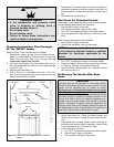
The Discharge Line/Driptube:
• Must not be smaller than the pipe size of the relief valve
or have any reducing coupling installed in the discharge
line.
• Must not be capped, blocked, plugged or contain any
valve between the relief valve and the end of the dis-
charge line.
• Must terminate a maximum of 300mm (12 in.) (Canada)
or 150mm (6 in.) (U.S.A.) above the floor.
• Must be capable of withstanding 121°C (250°F) without
distortion.
• Must be installed to allow complete drainage of both the
valve and discharge line.
NOTE: Rear and Combination flue units must be fitted with
a T&P Relief Valve WATTS type 40XL-5 or equivalent.
Failure to install and maintain a new, properly listed
temperature and pressure relief valve will release the
manufacturer from any claims which may result from
excessive temperature or water pressure.
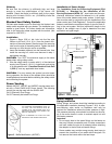
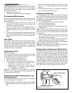
Vacuum Relief Valves
A vacuum relief valve, installed in the cold water supply line
above the top of the water heater, shall protect the water
heater against siphoning (loss of water due to loss of supply
pressure). Where heating equipment has a bottom supply,
the cold water supply piping shall be carried above the top
of the heater before being routed to the supply connection
and have a vacuum relief valve installed in it at a level above
the top of the storage tank. The vacuum relief valve shall be
in compliance with the latest edition of “Standard For Relief
Valves For Hot Water Supply Systems, ANSI Z21.22/CSA
4.4”.
WARNING
Explosion Hazard
• If the temperature and pressure relief
valve is dripping or leaking, have a
licensed plumber repair it.
• Do not plug valve.
• Do not remove valve.
• Failure to follow these instructions can
result in death or an explosion.