


Installation
312349G 9
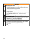
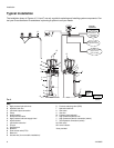
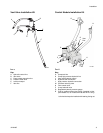
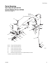
Vent Valve Installation Kit
FIG. 5
Key:
A Hydraulic control line
B Vent valve
C Pump output connection line
D Pressure relief valve
E Lubricant output
F Vent line
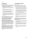
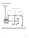
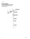
Control Module Installation Kit
FIG. 6
Key:
G Pump tank line
H Pump high pressure hydraulic line
J Vent valve hydraulic control
K Hydraulic tank connection
L High pressure hydraulic connection
M Pressure reducing valve
N Flow control valve
P 3-way solenoid valve
Q Regulated hydraulic pressure gauge
R Plug for systems without vent valves. (Installed in Vent
port instead of J, for models 247706 and 247707 only).
*coil should always be installed with lettering facing out
A
B
C
D
E
F
ti9647a
ti11457
Q
*
P
M
N
K
J
H
G
L
Vent
Port
R