


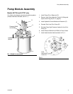
Installation
8 312349G
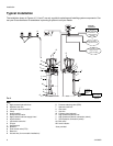
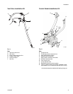
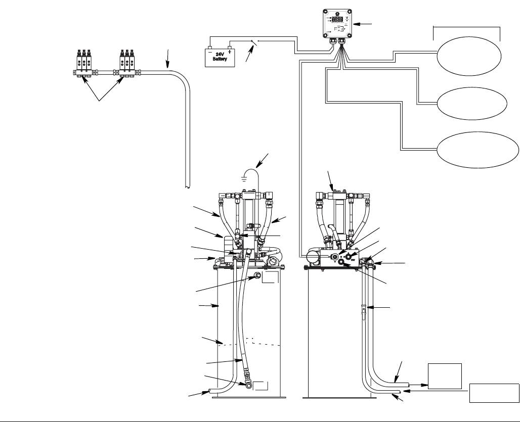
Typical Installation
The installation shown in Figures 4, 5, 6 and 7 are only a guide for selecting and installing system components. Con-
tact your Graco distributor for assistance in planning a system to suit your needs.
Key:
A High pressure hydraulic lines
B Hydraulic tank line
C Lubricant output connection
D Pump
E Ignition switch*
F 3-Way solenoid valve
G High-pressure lubricant supply lines*
H Injector banks*
J Lubrication controller*
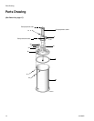
K Fill port
LOverflow port
M Breather
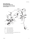
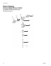
N Flow control valve (FCV)
P Reservoir
R Ground wire (for non-mobile installation)*
S Pressure reducing valve (PRV)
T Hydraulic tank line*
U Vent valve
V Vent line
W Follower plate (optional)
X High pressure hydraulic line*
Y High pressure hydraulic connection (swivel)
Z Tank hydraulic connection (swivel)
AA Ball valve*
AB Level indicator
*User provided
FIG. 4
H
G
E
J
R
D
B
A
AB
C
M
L
P
W
V
K
G
F
N
Y
Z
S
AA
T
X
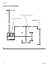
Hydraulic
Reservoir
Return
From Hydraulic
Power Supply
Front Back
Low Reservoir
Level Switch
(Level Indicator,
optional)
Pressure Switch
for System Control
Remote Alarm Device
(Light or Horn)
(user provided
Controller
Capabilities
U
ti09649b