


Unpacking
4 312349G
Unpacking
The Dyna-Star pump module was carefully packaged for
shipment by Graco. When the package arrives, perform
the following procedure to unpack the units:
1. Inspect the shipping box carefully for shipping
damage. Contact the carrier promptly if damage is
discovered.
2. Unseal the box and inspect the contents carefully.
There should not be any damaged parts.
3. Compare the packing slip against all items included
in the box. Any shortages or other inspection
problems should be reported immediately.
4. Store the box and packing materials in a safe place
for future use. Graco recommends that all packing
materials be saved in case the unit needs to be
shipped again.
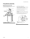
Pump Module Overview
Pump Module Capabilities
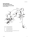
Pump Modules 247444 and 247574 for
Injector-based, Automatic Lubrication Systems:
provide lubricant flow and pressure to operate a single
line parallel automatic lubrication system. The module
requires a hydraulic power supply and a timed signal
from a lubrication controller. Based on these signals, the
pump module provides lubricant flow and pressure to
operate the injectors and vents the injector system to
reset the injectors.
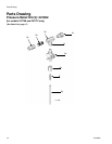
Pump Modules 247706 and 247707 for Single Line,
Series Progressive-based, Automatic Lubrication
Systems: provide lubricant flow and pressure to
operate a single line, series progressive, automatic
lubrication system. The module requires a hydraulic
power supply and a timed signal from a lubrication
controller.
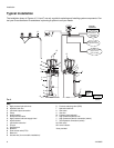
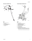
Pump Module Operation
(See FIG. 4, page 8)
Cycles for Pump Modules 247444 and 247574 for
injector-based, Automatic Lubrication Systems
1. Upon receiving a signal from a 24-volt Lubrication
Controller (J), the 3-way Solenoid Valve (F) opens,
starting the Pump (D) and closes the Vent Valve (U).
2. The pump builds pressure until the pressure switch
in the system sends a signal to the Lubrication
Controller (J), ending the cycle or Pump (D) stalls.
3. The Lubrication Controller (J) terminates the 24-volt
signal to the 3-way Solenoid Valve (F).
4. The 3-way Solenoid Valve (F) closes, stopping the
Pump (D) and opening the Vent Valve (U) into the
Reservoir (P).
5. The Pressure Reducing Valve (S) and Flow Control
Valve (N) control the pump output pressure and
cycle rate.
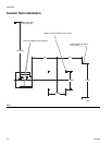
Cycles for Pump Modules 247706 and 247707 for
Single Line, Series Progressive-based, Automatic
Lubrication Systems
1. Upon receiving a signal from the 24-volt Lubrication
Controller (J), the 3-way Solenoid Valve (F) opens;
starting the Pump (D).
2. The Pump (D) provides lubricant flow and pressure
until the Lubrication Controller (J) terminates the
signal to the 3-way Solenoid Valve; stopping the
Pump.
3. The Pressure Reducing Valve (S) and Flow Control
Valve (N) control the pump output pressure and
cycle rate.