


Installation
6 312349G
Installation
Read instruction manual 312350 BEFORE installing this
product.
Grounding (for non-mobile installation)
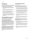
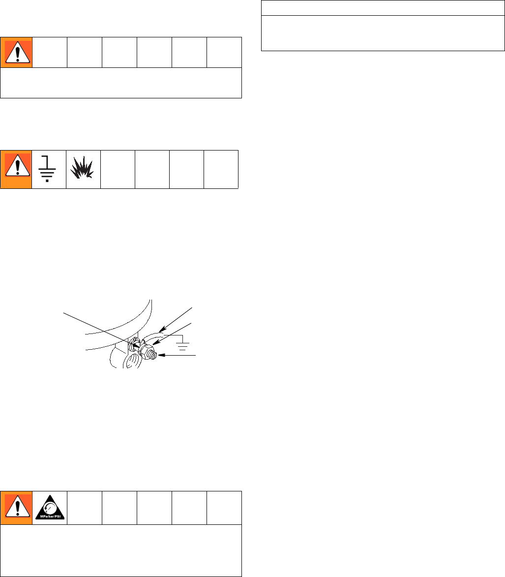
(See FIG. 3 below)
1. Loosen grounding lug locknut (A) and washer (B).
2. Insert one end of a 12 gage (1.5 mm
2
) minimum
ground wire (C) into slot in lug (D). Tighten locknut
securely.
3. Connect other end of wire to true earth ground. To
order a ground wire and clamp, order part number
222011.
F
IG. 3
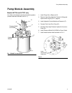
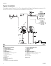
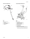
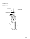
Pump Module
(See FIG. 4, page 8)
Mount Reservoir (P) on sturdy, flat surface with 6 (six),
3/8-inch diameter bolts. Note location of Fill Port (K),
Hydraulic Lines (A) and Lubricant Outlet Connection (C)
for easy access once installed.
1. Install Ball Valve (AA) (user provided) in the 3/8-inch
High Pressure Hydraulic Line (X).
2. Connect the 3/8-inch High Pressure Hydraulic Line
(X) to the High Pressure Hydraulic Connection
swivel (Y).
3. Connect the 3/4-inch Hydraulic Tank Line (T) to the
Tank Hydraulic Connection swivel (Z).
4. Connect the 24 VDC timer controlled signal to the
3-way Solenoid Valve (F).
5. Connect High Pressure Lubricant Supply Line (G) to
the Lubricant Output Connection (C) for Single Line
Parallel Systems or to Pressure Relief Kit Output
Connection for Single Line, Series
Progressive-based Systems.
6. Ground system (see GROUNDING). Mount
Reservoir (P) to grounded chassis member.
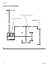
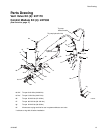
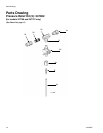
Vent Valve Kit for Custom Tank Installation
(Unless otherwise indicated, see FIG. 5 and FIG. 6, page
9)
1. Weld the bracket (F
IG. 7, page 10) in place per
recommended configuration for mounting the vent
valve. Paint the bracket if desired.
2. Connect the Hydraulic Control Line (A) to control
module Vent Valve Hydraulic Control (J).
3. Connect Pump Output Connection line (C) to Pump
outlet.
4. Connect the High Pressure Lubricant Supply Line
(G, F
IG. 4, page 8) feeding the injector system to the
Lubricant Output (E).
5. Connect the Vent Line (F) to Custom Tank (user
provided).
• Be sure unit is securely mounted before operation.
• Do not lift pressurized equipment.
• The hydraulic system must be depressurized before con-
necting High Pressure Hydraulic Lines (A).
• Be sure Breather (M) is not plugged before filling Reser-
voir (P).
A
CB
D
ti0720
CAUTION
The hydraulic supply must be 10µ filtered or better and sup-
ply 0.5 - 3.0 gpm (1.9 - 11.4 lpm) at 300 psi - 3500 psi (21
bar - 241 bar (2.1 MPa - 24 MPa).