


Installation
312349G 7
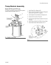
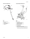
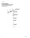
Hydraulic Control Module for Custom Tank
Installation
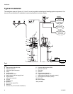
(Unless otherwise indicated, see FIG. 5 and FIG. 6, page
9)
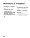
1. Mount control module on a flat, sturdy surface per
the recommended configuration (Fig. 2, page 8).
2. Connect Pump Tank Line (G) to pump hydraulic
outlet port.
3. Connect Vent Valve Hydraulic Control (J)
connection to the hydraulic control line (A).
4. Connect the Pump High Pressure Hydraulic Line
(H) to the pump hydraulic input port.
5. Connect high pressure hydraulic supply to the High
Pressure Hydraulic Connection (L) and the tank
lines to the Hydraulic Tank Connection (K).
6. Connect the 3-way Solenoid Valve (P) to the timer.
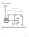
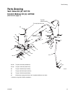
Hydraulic Control Module 247705
(For Single-line, Progressive, Automatic Lubrication
Systems with refinery reservoir installation)
(Unless otherwise indicated, see F
IG. 5 and FIG. 6, page
9)
1. Mount control module on a flat, sturdy surface. The
6-foot hydraulic supply and hydraulic tank line must
reach the pump when installed in the refinery
reservoir.
2. Connect Pump Tank Line (G) to pump hydraulic
outlet port.
3. Remove Vent Valve Hydraulic Control (J) and add
plug (R) to vent port.
4. Connect the Pump High Pressure Hydraulic Line
(H) to the pump hydraulic input port.
5. Connect high pressure hydraulic supply to the High
Pressure Hydraulic Connection (L) and the tank
lines to the Hydraulic Tank Connection (K).
Coil should always be installed with lettering facing
out.