


Operation
312349G 11
Operation
Pressure Relief Procedure
Models 247444, 247574, 247456, 247457,
247970
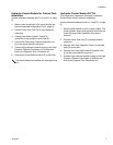
(See FIG. 4, page 8.)
1. Disable hydraulic supply to Pump (D) by isolating it
from the high pressure hydraulic supply using Ball
Valve (AA).
2. Do one of the following:
• Open Pressure Reducing Valve (S) to reduce
trapped hydraulic pressure,
or
• Cycle the timer to open the 3-way solenoid
valve to reduce trapped hydraulic pressure.
3. Disconnect power from Lubrication Controller (J).
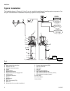
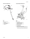
Models 247706, 247707
(For these instructions see FIG. 4, page 8.)
1. Disable hydraulic supply to Pump (D) by isolating it
from the high pressure hydraulic supply using Ball
Valve (AA).
2. Disconnect power from Lubrication Controller (J).
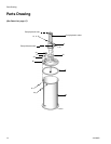
3. Place a container under plastic tube (5g, page 16) in
Pressure Relief Kit (247902) to catch fluid when
relieving pressure.
4. Open ball valve (5d, page 16) in Pressure Relief Kit
(247902).
Start-up
(For these instructions see FIG. 4, page 8.)
Prime Vent Line Models 247444 & 247574
The first time the reservoir is filled, use the vent valve
outlet. This removes all air from the vent line (V).
1. Connect lubricant supply hose from remote filling
station pump unit to outlet of Vent Valve (U).
2. Remove plug in Fill Port (K) located at bottom of
reservoir.
3. Slowly turn on supply lubricant until lubricant
appears in fill port.
4. Remove lubricant supply hose from vent valve.
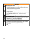
To reduce the risk of serious injury follow this pressure
relief procedure whenever you (are):
• Instructed to relieve pressure.
• Shut off pump.
• Check, clean or service any of the system equip-
ment.
• Install or clean the dispensing valve.
Gauge on control module should read zero pres-
sure after performing this step.
Do not insert finger into the overflow port while filling
a reservoir equipped with a follow plate. Injury or
amputation could result.