


6 307932
Installation
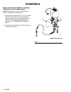
Supplied Components
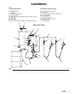
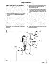
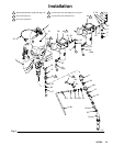
Refer to Fig. 2 for a typical installation of an airless
system.
WARNING
A red-handled bleed-type master air valve (14) and
a fluid drain valve (7) are supplied in your system.
These accessories help reduce the risk of serious
injury, including fluid injection and splashing of fluid
in the eyes or on the skin, and injury from moving
parts if you are adjusting or repairing the pump.
The red-handled bleed-type master air valve re-
lieves air trapped between this valve and the pump
after the air is shut off. Trapped air can cause the
pump to cycle unexpectedly. Locate the valve close
to the pump.
The fluid drain valve assists in relieving fluid pres-
sure in the displacement pump, hose, and gun.
Triggering the gun to relieve pressure may not be
sufficient.
D The red-handled bleed-type master air valve
(14) is required in your system to relieve air trapped
between it and the air motor when the valve is
closed (see the WARNING above). Be sure the
bleed valve is easily accessible from the pump, and
is located downstream from the air regulator.
D The air regulator (8) controls pump speed and
outlet pressure by adjusting the air pressure to the
pump. Locate the regulator close to the pump, but
upstream from the red-handled bleed-type master
air valve (14).
D The air manifold (15) has a swivel air inlet. It
mounts to the cart, and provides ports for connect-
ing lines to air-powered accessories.
D The fluid filter (4) includes a 60 mesh (250 mi-
cron) stainless steel element to filter particles from
the fluid as it leaves the pump.
D The fluid drain valve (7) is required in your sys-
tem to relieve fluid pressure in the hose and gun
(see the WARNING above).
D The suction hose (24) and tube (25) allow the
pump to draw fluid from a 200 liter (55 gallon)
drum.
System Accessories
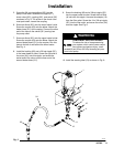
Air and Fluid Hoses
Be sure all air hoses (A) and fluid hoses (G) are prop-
erly sized and pressure-rated for your system. Use
only electrically conductive hoses.
1. Connect one end of the fluid line (G) to the filter
outlet swivel. Connect a fluid hose to each gun (H).
Install a fluid shutoff valve (J) at each gun drop.
Do not install the spray tip in the gun yet.
2. Close the red-handled bleed valve (14) and air
regulator (8). Connect the air hose (A) to the
swivel inlet of the air manifold (15).
Air Line Accessories
1. Install an air line filter (B) in the main air line, to
remove harmful dirt and moisture from the com-
pressed air supply.
2. Install a second bleed valve (C) in the main air
line, to isolate the accessories for servicing.
3. Install a drain valve (D) at the bottom of each air
line drop, to drain off moisture.
4. To provide automatic lubrication of the air motor,
install an air line lubricator (E) downstream from
the red-handled bleed-type master air valve (14).
5. Install a pump runaway valve (F). The runaway
valve will automatically shut off the air to the pump
if the pump starts running too fast. A pump that
runs too fast can be seriously damaged.