


10 307932
Installation
Converting to a Heated System
To convert Model 245187 or 253697 to a heated
circulating system, order the following parts. The
heaters are available in three voltages. Specify which
voltage you desire.
D Two Viscon HP Fluid Heaters
– Model 245848 (120 V, single-phase, 19.2 amp)
– Model 245863 (240 V, single-phase, 16.7 amp)
– Model 245864 (480 V, single-phase, 8.30 amp)
D Dual Heater Mounting Kit 222311
D Circulating Kit 222312
D Warning Label 290074
WARNING
The Viscon HP Heaters must be installed by a
qualified electrician in compliance with all state and
local codes and regulations, to reduce the risk of
electric shock or other serious injury during installa-
tion or operation.
The power supply must match the heaters’ require-
ments (see above). Refer to the Viscon HP Heater
Manual, 309524, for further information.
Accessories for a Heated System
Viscon HP Heater Cord 110160
12 gauge, rated at 105_ C.
WARNING
Do not use in hazardous areas containing flam-
mable materials or fumes.
Airless Insulated Hose Kit 222263
25 ft. (7.6 m) nylon fluid hose for use with airless
heated systems. Includes an in-line fluid filter, circulat-
ing manifold, and 3 ft. (0.9 m) whip hose.
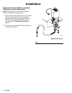
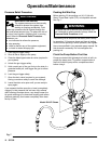
Installing Dual Heater Mounting Kit 222311
WARNING
Before installing the heaters, dual heater mounting
kit and circulating kit, follow the Pressure Relief
Procedure on page 14. Disconnect all hoses from
the pump.
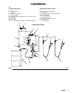
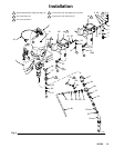
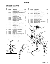
NOTE: Reference numbers marked with an asterisk
(for example, 26*) are included in kit 222311.
Apply pipe sealant (36*) to all male threads except at
swivel connections.
1. Be sure the wall is strong enough to support the
weight of the heaters, hoses, fluid, and stress
caused during operation. Locate the holes for the
heater wall brackets (26*) exactly as indicated on
page 20. Note that one heater will be mounted
above and slightly to the left of the other. Use the
heater wall brackets as templates to mark the wall.
2. Attach a heater wall bracket to each heater’s
mounting posts with the M8 x 1.25 screws and
lockwashers supplied with the heater (44).
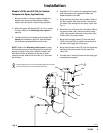
3. Use M8 or 5/16 in. bolts of the appropriate length
and lockwashers (not supplied) to fasten the
heater brackets to the wall.
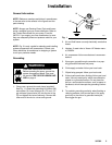
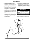
4. Remove the fluid filter (4) and attaching hardware
(3, 9) from the pump fluid outlet. Keep the filter,
but discard the attaching hardware. See Fig. 5.