


307843 9
Installation
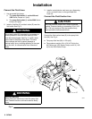
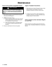
Connect the Air Lines
1. Install the air line accessories to the left of the
pump as shown in Fig. 4. Mount these accessories
on the wall or on a bracket. Be sure the air line
supplying the accessories is grounded.
2. Install a flexible air hose between the accessories
and the 1/2 in. npt(f) air inlet (G). Use a minimum
1/2 in. ID air hose.
3. Install an air line lubricator (B) upstream from the
pump air inlet for automatic pump lubrication.
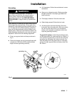
4. Install a pump runaway valve (T) to sense when
the pump is running too fast and shut off the air
supply to the motor. To order a pump runaway
valve, order Part No. 224040.
5. Install an air regulator (D) to control air inlet pres-
sure.
WARNING
A bleed-type master air valve (C) is required in
your system to relieve air trapped between this
valve and the pump after the air regulator is closed.
Trapped air can cause the pump to cycle unexpect-
edly, which could result in serious bodily injury,
including splashing in the eyes, injury from moving
parts, or contamination from hazardous fluids.
6. Install one bleed-type master air valve (C) down-
stream from the air regulator and use it to relieve
trapped air. Locate the other master air valve up-
stream from all air line accessories and use it to
isolate the accessories during cleaning and repair.
7. Install an air line filter (A) to remove harmful dirt
and moisture from your compressed air supply.
8. Install a grounded air supply line (P) with a mini-
mum 1/2 in. ID. See Fig. 4.
Ventilate the Air Exhaust
WARNING
Improper handling of hazardous fluids or inhaling
their vapors can cause serious bodily injury, even
death. For your safety, it is imperative that you read
all product warning labels and Material Safety Data
Sheets (MSDS) for the fluids you are using. An
MSDS can be obtained from your fluid suppliers. It
is also important that you read and understand the
warnings and precautions regarding HAZARDOUS
FLUID HAZARD on page 5 before you operate.
All systems using hazardous fluid in enclosed
areas or within buildings should have a properly
designed and installed ventilation system. Consult
your local building code and other industrial and
governmental standards for proper design criteria.
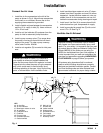
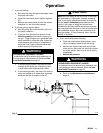
Fig. 4
KEY
A Air line filter
B Air line lubricator
C Bleed-type master air valve
D Air regulator
E Fluid drain valve
F Fluid filter
G Pump air inlet
H Grounded fluid line
J Outlet manifold
K Main air line
L Ground wire
M Intake manifold
N Glutton pump
P Grounded air line
R Fluid supply
S Fluid suction hose
T Runaway valve
0232
3
K
C
C
D
AB
T
G
L
N
JF
H
S
R
M
E
P