


16 307843
Service
Assembly
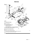
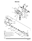
1. Slide the retaining plate (20), bellows (14*), and
intake housing (36) onto the piston shaft (15). Do
not force the bellows. Repeat on the other side.
CAUTION
To avoid damaging the bellows (14), do not force it
onto the shaft. The bellows will press into place when
the piston (17) is secured.
2. Install the piston (17) on the shaft (15) and secure
it with the screw (16). Repeat on the opposite end
of the pump.
3. Using a socket and breaker bar, torque one screw
(16) to 40 to 50 ft-lb (54 to 67 NSm), then repeat
with the other screw.
4. Grease and install an o-ring (19*) in each inlet.
Install inlet manifold (47) with screws (32) and
washers (46 or 61). Don’t torque screws yet.
CAUTION
To avoid loosening the piston stud (30) during disas-
sembly, do not overtighten the screws (16).
NOTE: If using a formed UHMWPE seal, proceed to
step 5. If using a flat nylon seal, proceed to step 6.
5. Grease and install the o-ring (18*) in the groove in
the tapered side of the retaining plate (12). Grease
the outlet housing (33) and install the piston seal
(13*) and retaining plate (12). Be sure the flat side
of the retaining plate faces the piston seal. Secure
with the four screws (34) and washers (35).
6. Apply 10 psi air to move the piston to one side and
hold it there. Replace the o–ring (18*) in the
groove in the tapered side of the retaining plate
(12).
Grease the oulet housing groove and set the nylon
seal (13) inside the groove. Carefully tip the hous-
ing (33) onto the inlet housing. Be sure the flat side
of the retaining plate (12) faces the piston seal.
Secure with the four screws (34) and washers
(35).
Increase the air pressure to about 50 psi until the
pump cycles and the piston drives to the other
side.
Reduce the air pressure to 10 psi to hold in posi-
tion. Repeat the seal installation pattern.
Increase the air pressure to 50 psi again to cause
the pump to cycle again and form the seal on the
first side.
NOTE: Torque the screws, on 400 and 1200 Series
pumps, to 40 to 50 ft-lb (54 to 68 N-m). Torque the
screws on the 2500 Series pump, to 35 to 40 ft-lb (47
to 54 N-m).
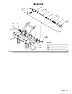
7. Torque the inlet manifold screws (32) to 7.4 to 12.5
ft-lb (10 to 17 N-m).
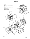
8. Replace the o-ring (52*) in each outlet manifold
connector (51) and lubricate the threads. Install the
outlet manifold (50), torquing the connectors to 55
to 85 ft-lb (75 to 115 NSm).
NOTE: On stainless steel pumps (Models 220666
through 220668 and Models 237011 to 237013), apply
anti-seize lubricant to the threads of the connector
(51).