


18 307843
Service
Repairing the Air Motor and Piston
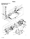
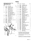
NOTE: Parts marked with an asterisk are included in a
repair kit, for example, (23*). See pages 38 and 39 for
repair kit part numbers. Use all the parts in the kit for
the best results.
Disassembly
1. Relieve the pressure.
WARNING
PRESSURIZED EQUIPMENT HAZARD
To reduce the risk of a serious injury whenever you
are instructed to relieve pressure, follow the Pres-
sure Relief Procedure on page 10.
2. Disassemble the pump as instructed under Re-
pairing the Fluid Piston and Seal.
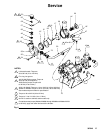
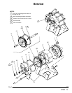
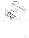
3. Remove the screws (3 & 4), washers (46), nuts
(1), and lockwashers (2) from the cylinder cap
(25). See Fig. 7.
4. Remove the pump from the mounting bracket (44).
5. Remove the cylinder cap (25) from each end of the
air motor. If the hoses aren’t disconnected or the
pilot valves removed, be careful not to pull on the
hoses when removing the caps.
CAUTION
The shaft wiper (21) and bearing (22) are meant to
remain in place. Remove only to replace. Removal
will damage them.
6. Remove the shaft wiper (21) and bearing (22); only
if they need to be replaced, and u-cup (23*) from
each of the cylinder caps (25). Use a 0.875 in. di-
ameter shaft to remove the bearing.
7. Remove the piston assembly (A) from the air mo-
tor cylinder (27). Remove the seal (28).
8. Do not remove the piston shafts (15) unless re-
placement is necessary as a high strength sealant
was used on the threads. If the rods must be re-
moved, heating the joint to 300_ F will ease disas-
sembly. Place wrenches on the flats of the piston
shaft to disconnect them from the piston stud (30).
9. Clean all parts and inspect for wear or damage.
Replace as needed.
Assembly
1. Apply lithium base grease to all packings, seals,
and the inside of the air motor cylinder (27) before
assembling.
2. If the piston shafts (15) were removed from the
piston stud (30), apply high strength sealant (such
as Loctiter) to the threads of the piston stud, and
assemble as shown in Fig. 7.
3. Install the quad ring (28*) in the groove on the pis-
ton (29). Install the piston assembly (A) into the air
motor cylinder (27).
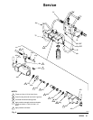
4. Install a u-cup (23*) into each of the cylinder caps
(25). The lips of the u-cup must face in, towards
the center of the pump, as shown in Fig. 8.
5. If the bearings (22) were removed, install a bearing
into each cylinder cap (25). Press fit the bearing to
flush, using an arbor press.
6. Install a shaft wiper (21) into each cylinder cap
(25) with the brass part of the wiper facing out,
away from the center of the pump, as shown in
Fig. 8. Carefully press the wiper into place, taking
care to avoid damaging the brass piece.
7. Install an o-ring (26*) into the groove in each of the
cylinder caps (25). Slide a cylinder cap (25) onto
each end of the air motor. Align flat edges with air
valve.
8. Secure the mounting bracket (44) and cylinder
caps (25) on the pump with the screws (3 and 4),
washers (46), nuts (1), and lockwashers (2). Tor-
que the screws oppositely and evenly to 7.4 to
12.5 ft-lb (10 to 17 NSm).