


20 307843
Service
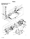
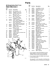
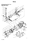
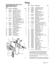
Repairing the Air Control Valve
NOTE: Air Valve and Pilot Valve Repair Kit 220656 is
available. See page 38 to order. Parts included in the
kit are marked with an asterisk, for example, (40p*).
Use all the parts in the kit for the best results.
Disassembly
1. Relieve the pressure.
WARNING
PRESSURIZED EQUIPMENT HAZARD
To reduce the risk of a serious injury whenever you
are instructed to relieve pressure, follow the Pres-
sure Relief Procedure on page 10.
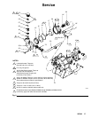
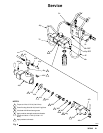
2. Cut a small slit in the tube ends (72*, 42*, 40p*)
and disconnect them from the pilot valve fittings
(5h), air valve tees (40n), and barb fittings (40s).
See Fig. 8.
3. Remove the valve end housings (40b) by unscrew-
ing the screws (40k) and nuts (40m).
4. Center the valve spools (40c) in the housing (40a).
Remove the spools and stem (40d) by applying
opposing force with wrenches on the spool (40c)
flats.
5. If the air filter (40q) needs cleaning or replace-
ment, unscrew the filter housing (40r) and remove
the filter. To clean them, soak the filter housing and
the filter in solvent until they are clean. Blow them
dry with low pressure air [under 30 psi (207 MPa,
2.1 bar)]. Press fit the filter into the housing, using
40 to 60 lb (18 to 27 kg) of force. Refer to Fig. 8.
Apply sealant to the filter housing threads and turn
it into the center housing (40a).
Assembly
1. Apply lithium-base grease to all o-rings, u-cups,
gaskets and to the complete spool assembly be-
fore installing them.
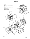
2. Remove the seal retainers (40e) from each side of
the center housing (40a). Replace the u-cup (40j*),
with the lips facing into the housing. Install the re-
tainers with the flat side facing into the housing.
3. Replace the spools (40c) if damaged. Replace the
o-ring (40h*) and u-cup (40i*) on each spool, being
sure to seat them in the grooves. Install the u-cup
with the lips facing towards the housing (40a).
4. Apply medium strength thread sealant to the spool
stem (40d) threads. Remove the excess sealant.
5. Thread one spool (40c) onto the stem (40d) and
insert it into the center housing (40a); be careful
not to dislodge the u-cups (40j) and retainers
(40e). Thread the other spool onto the stem. With
wrenches on the flats of the spools, apply oppos-
ing force and tighten until snug; 7 to 13 in-lb (0.79
to 1.47 NSm). Do not overtighten.
CAUTION
Do not overtighten the spools (40c) as this can
shear the spool threads.
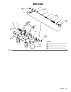
6. Replace the gasket (40f*) in each end housing
(40b) and the o-ring (40g*) on each end housing
shoulder.
7. With the mufflers facing down, install the end
housings (40b), onto the center housing (40a); be
careful not to move the spool and dislodge the u-
cups (40j) and retainers (40e). Secure the end
housings with the four screws (40k) and nuts
(40m), torquing them to 2.2 to 3.7 ft-lb (3 to 5
NSm).
CAUTION
If mufflers (38) are replaced, they must be installed
with the lock rings (39) to avoid damage to the spool
and o-rings during operation.
8. Replace the two o-rings (40h*) in the center hous-
ing (40a).
9. Install the air valve on the pump with the four cap
screws (43). Torque them alternately and evenly to
2.2 to 3.7 ft-lb (3 to 5 NSm).
10. Connect the new tubes (72*, 42*, 40p*) to the pilot
valve fittings (5h), air valve tees (40n), and barb
fittings (40s), as shown in Fig. 8.