


307843 15
Service
Repairing the Ball Check Valves
NOTE: Parts marked with an asterisk are included in a
repair kit, for example, (54*). See pages 38 and 39 for
repair kit part numbers. Use all the parts in the kit for
the best results.
Disassembly
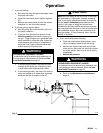
1. Relieve the pressure.
WARNING
PRESSURIZED EQUIPMENT HAZARD
To reduce the risk of a serious injury whenever you
are instructed to relieve pressure, follow the Pres-
sure Relief Procedure on page 10.
2. Disconnect the air and fluid lines, remove the
pump from its mounting, and place it on a bench.
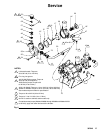
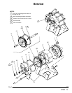
3. Remove the cap (53) from each side of the outlet
housing (33). See Fig. 6.
4. Remove the ball guide (56), ball (57), valve seat
(49), and o-ring (48*) on each side of the outlet
housing.
5. Inspect the ball stop (55) inside the cap (53) for
wear. Remove o–ring (54). Replace if necessary.
6. Clean all parts and inspect for wear or damage.
Replace as needed.
Assembly
1. Lubricate the o-rings (48*) and place one in the
groove on each valve seat (49).
2. Install the valve seat (49) with the o-ring (48) fac-
ing down, ball (57), and ball guide (56) into each
outlet housing (33).
NOTE: Stainless steel seats are reversible.
3. Lubricate the o-rings (54*) and the cap (53)
threads. Place one o-ring on each cap. Screw the
caps into the housing and torque them to 55 to 85
ft-lb (75 to 115 NSm).
NOTE: On stainless steel pumps (Models 220666
through 220668 and Models 237011 to 237013), apply
anti-seize lubricant to the threads of the cap (53).
Repairing the Fluid Piston and Seal
NOTE: Parts marked with an asterisk are included in a
repair kit, for example, (52*). See pages 38 and 39 for
repair kit part numbers. Use all the parts in the kit for
the best results.
Disassembly
1. Relieve the pressure.
WARNING
PRESSURIZED EQUIPMENT HAZARD
To reduce the risk of a serious injury whenever you
are instructed to relieve pressure, follow the Pres-
sure Relief Procedure on page 10.
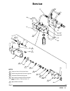
2. Loosen the tube nuts (A) and remove the outlet
manifold (50). Unscrew the connectors (51). Re-
move the o–ring (52). See Fig. 6.
3. Remove the screws (34), washers (35), outlet
housing (33), piston seal (13*) and retaining plate
(12). Remove the o–ring (18). Repeat on the other
side of the pump.
4. Holding the screw (16) on one side of the pump,
loosen the screw three or four turns on the oppo-
site side of the pump, using a socket and breaker
bar.
5. Remove the piston (17) by grasping it with your
hand and and hit screw (16) with a plastic mallet to
drive piston loose from shaft. Remove screw (16)
and piston (17).
6. Remove the screws (32), washers (46 or 61), and
inlet manifold (47). Remove o–rings (19).
7. Remove the intake housing (36), bellows (14*),
and retaining plate (20).
8. Holding the piston shaft (15) flats with a wrench,
remove the remaining screw (16).
9. Repeat steps 6 and 7 on the opposite end of the
pump. Clean all parts and inspect for wear or dam-
age. Replace as needed.