


Remote Control Thermostat
Installation
Install Thermostat
1. Approximately 5 ft. from the
2. Close to or in a frequently used room, preferably on an inside wall.
3. On a section of wall without pipes or ductwork.
The Thermostat should NOT be mounted:
1. Close to a window, on an outside wall, or next to a door leading
outside.
2. Where it can be exposed to direct sunlight or heat,such as thesun,
a lamp,
or any temperature radiating object which
may cause a false reading.
3. Close to or in the direct
of supply registers and/or return
air grilles.
4. Any areas with poor air circulation, such as a corner, behind a
door, or an alcove.
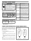
Remote Thermostat and Low
Voltage Control Connections
Remote Thermostat
All Friedrich PD model PTAC units are factory
to be controlled
by either the chassis mounted Smart Center or a24V remote wall mounted
thermostat. The thermostat may be auto or manual changeover as long as
the control
matches that of the PTAC unit.
NOTE: All PDE models require a single stage cool, single stage heat.
thermostat. All PDH models require a single stage cool, dual.
stage heat thermostat with an O reversing valve control. The
Friedrich RT6 thermostat can be
for either model.
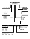
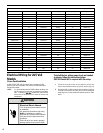
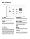
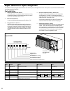
FRP029
F
RP029
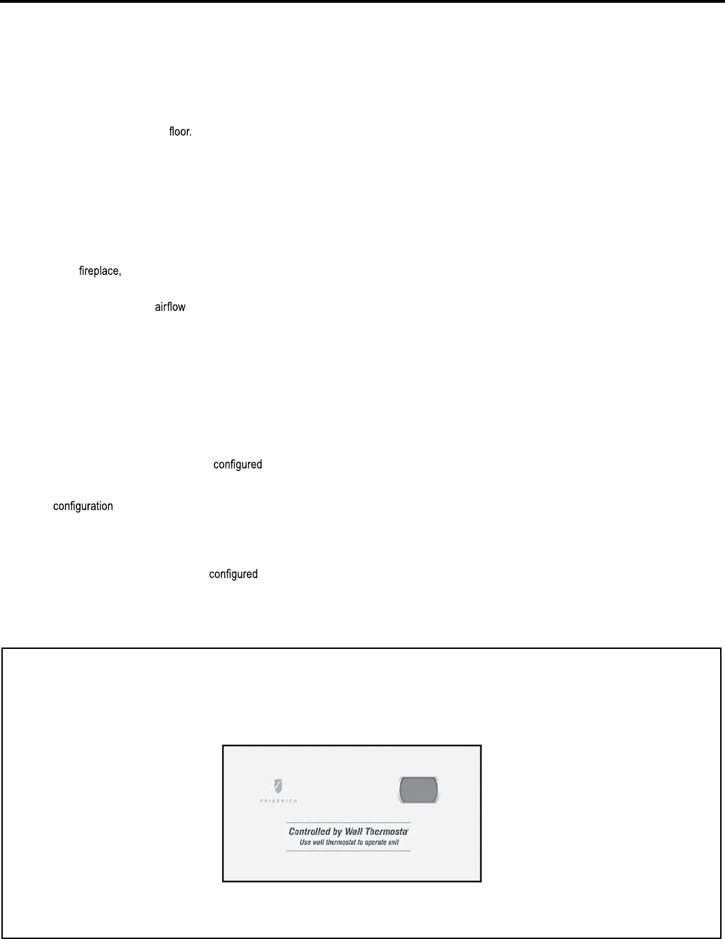
Control board with optional PDXRT escutcheon kit installed
To control the unit with a wall mounted thermostat
follow the steps below:
1. Unplug the unit before doing any work.
2. Withthe front.coverremoved locate thedip switches located below
the Smart Center control panel. Switch Dip switch 2 to the up on
'ON' position.
3. Remove the low voltage terminal block from the unit.
4. Connect the corresponding terminals from the wall thermostat to
the terminal block.
5. Replace the terminal block on the unit.
6. Restore power to the unit.
7. The unit is now controlled by the wall thermostat only.
8. If the accessory escutcheon kit (PDXRTA) is to be used, install it
over the existing control panel.
NOTE:. The unitmountedcontrolsno longercontrolthe unit. To restore
the unit mounted controls move dip switch 2 to the down or
'OFF' position.
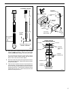
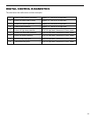
Thermostat Connections
R = 24V Power from Unit
Y = Call for Cooling
W =
=
Call for Heating
O Reversing Valve Energized in cooling mode (PDH Models Only)
GL = Call for Low Fan
GH = Call for High Fan
C = Common Ground
*If only one G terminal is present on thermostat connect to GL for low
speed fan or to GH for high speed fan operation.
18